Preheating catalytic-oxidation device with burner starting for coal mine ventilation air methane

A catalytic oxidizer and burner technology, applied in chemical/physical processes, chemical instruments and methods, etc., can solve the problems of large TFRR resistance loss, high maintenance cost, high fan energy consumption, etc., to reduce volume and floor space, Effects of improving operation economy and improving operation reliability

Inactive Publication Date: 2011-10-26
SHANDONG UNIV OF TECH
View PDF3 Cites 24 Cited by
  • Summary
  • Abstract
  • Description
  • Claims
  • Application Information

AI Technical Summary

Problems solved by technology

However, from the perspective of practical application, only the thermal countercurrent reaction technology has been successfully applied commercially in the coal mine field.
However, the use of TFRR technology to treat coal mine exhaust gas still has the following problems: (1) TFRR occupies a relatively large area, for example, the TFRR unit of MEGTEC Company needs to process 150m 3 / s gas, the device covers an area of ​​about (63×14.62×4.49) m; (2) The oxidation bed of TFRR is composed of a large number of honeycomb ceramics, and the honeycomb ceramics will crack, break and block after long-term use , Generally speaking, the honeycomb ceramics need to be replaced once a year, and the maintenance cost is too high; (3) The resistance loss of TFRR is very large, generally above 8000KPa, and the energy consumption of the fan is very high; (4) The airflow in the oxidation bed of TFRR needs to be constantly Change the direction to ensure that the high temperature area is maintained in the middle of the oxidation bed, which requires a high degree of automatic control and high operating technology requirements
These main problems increase the difficulty of popularization and application of TFRR technology

Method used


Image

  • Preheating catalytic-oxidation device with burner starting for coal mine ventilation air methane
  • Preheating catalytic-oxidation device with burner starting for coal mine ventilation air methane
  • Preheating catalytic-oxidation device with burner starting for coal mine ventilation air methane

Examples


Embodiment Construction

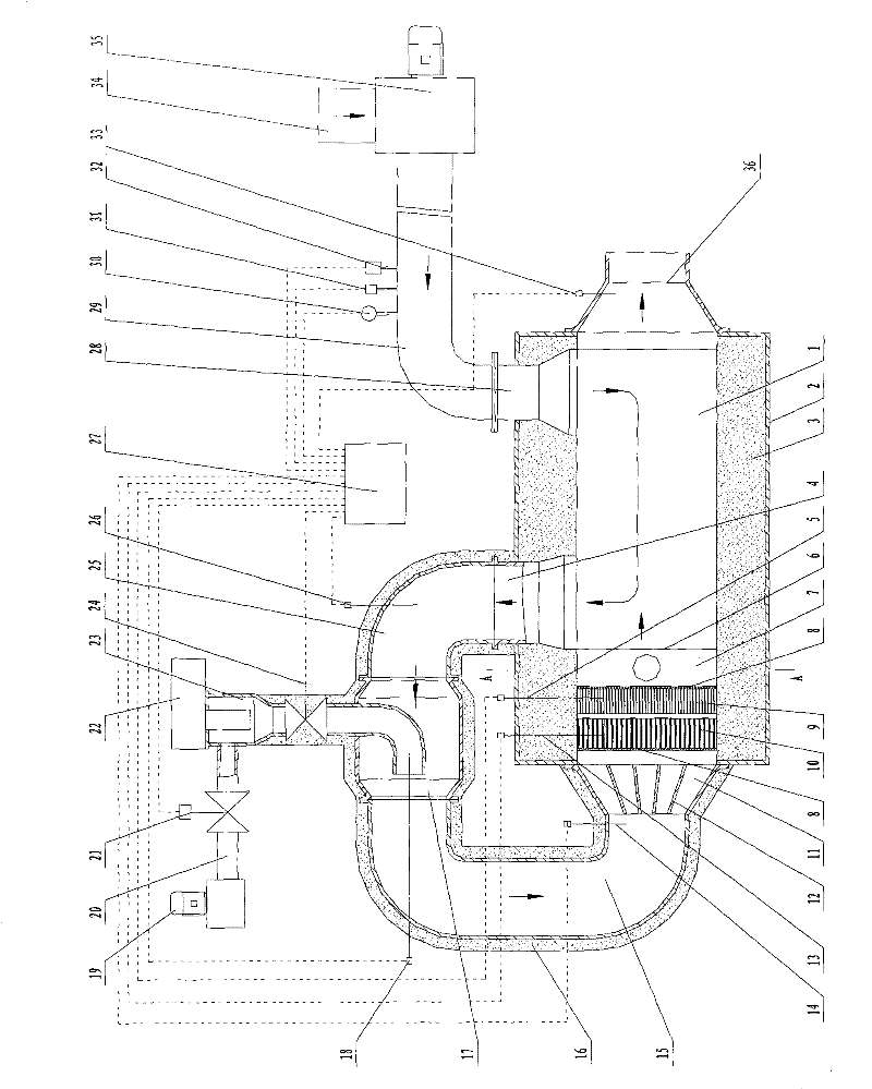
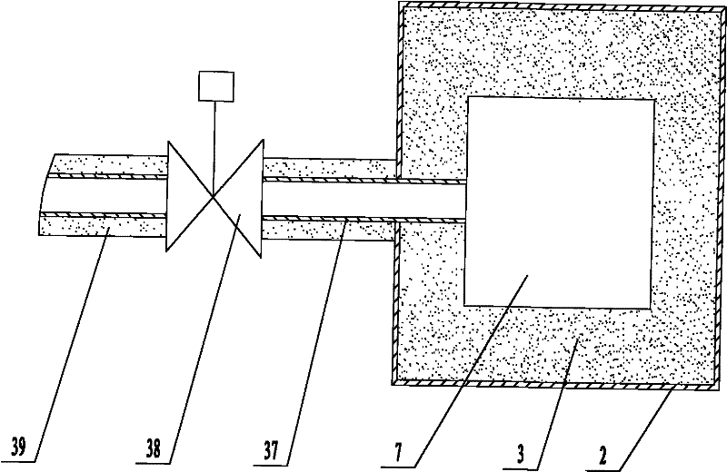
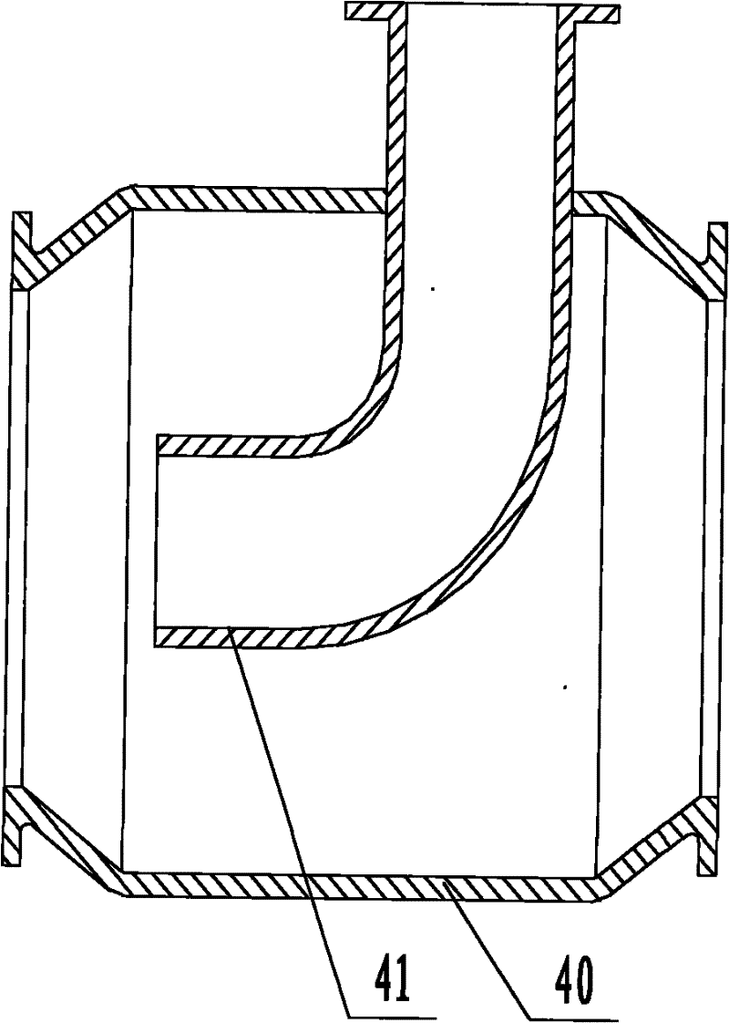
[0030] exist Figure 1-4 In the shown embodiment: coal mine exhaust air preheating catalytic oxidizer with burner start, including exhaust air supply system, preheater 1 and reaction chamber 7 arranged in shell 2, burner heating start system , air intake system, heat extraction system and measurement and control system, of which:

[0031] The exhaust air supply system includes a first exhaust air conveying pipeline 29, a second exhaust air conveying pipeline 34 and a main fan 35, wherein one end of the second exhaust air conveying pipeline 34 communicates with the exhaust exhaust outlet of the mine, and the other end passes through the main fan. 35 is connected to the first exhaust air conveying pipeline 29;

[0032] The inner wall of the housing 2 is provided with a first thermal insulation layer 3, the preheater 1 adopts a partitioned air-air heat exchanger, and the exhaust air inlet 28 of the preheater passes through the first thermal insulation layer 3 and extends to the ...


PUM


Abstract

The invention provides a preheating catalytic-oxidation device with burner starting for coal mine ventilation air methane, and belongs to the technical field of ultralow-concentration methane oxidation; the device comprises a ventilation air methane gas supply system, a preheater and a reaction chamber disposed in a housing, a burner heating starting system, a gas intake system, a heat extractionsystem, and a measuring and controlling system, wherein a uniform-temperature uniform-flow bed layer and a catalytic-oxidation bed layer are orderly disposed in the reaction chamber along the gas flow direction, and hot gas generated by the burner heating starting system is delivered into the gas intake system. After the starting of heating in the reaction chamber, the ventilation air methane is fed into the preheater to be heated to a high temperature, and is oxidized into carbon dioxide and water in the catalytic-oxidation bed layer; a part of the oxidized hot gas is allowed to enter the heat extraction system for heat extraction and utilization, and the other part is allowed to enter the preheater for transferring heat to fresh ventilation air methane entering the preheater and for cooling, and then is discharged into atmosphere through a exhaust gas outlet. The invention has the advantages of compact structure, low power dissipation, simple operation, high reliability, flexible fuels, and the like.

Description

technical field [0001] The invention relates to a device for catalytic destruction of ultra-low concentration coal mine gas, in particular to a coal mine exhaust air preheating catalytic oxidizer with a burner start, and belongs to the technical field of ultra-low concentration methane oxidation. Background technique [0002] my country's coal mines emit more than 15 billion Nm of gas into the atmosphere every year through exhaust wind 3 , On the one hand, it has caused a huge waste of limited non-renewable resources, and on the other hand, it has also aggravated air pollution and the greenhouse effect. The low concentration of exhaust gas in coal mines (generally fluctuating between 0.1% and 0.75%) is the main problem restricting its utilization. At present, the effective utilization methods are thermal countercurrent oxidation technology (Thermal Flow Reversal Reactor, referred to as TFRR) and catalytic countercurrent oxidation. Technology (Catalytic Flow Reversal, referr...

Claims


Application Information

Patent Timeline
Patent Type & Authority Applications(China)
IPC IPC(8): B01J8/02
Inventor 刘永启刘瑞祥王延遐郑斌高振强
Owner SHANDONG UNIV OF TECH
Why Eureka
Try Eureka