Packing machine

A technology of packing machines and racks, applied in the field of packing machines, can solve the problems of easy shaking, easy shaking, and increased power load when the translation frame moves horizontally.

Inactive Publication Date: 2012-02-22
GUANGZHOU TECH LONG PACKAGING MACHINERY CO LTD
View PDF5 Cites 21 Cited by
  • Summary
  • Abstract
  • Description
  • Claims
  • Application Information

AI Technical Summary

Problems solved by technology

But this translation type case packer still has deficiencies, as, 1, because translation frame and elevating frame realize horizontal movement and move up and down by first motor and second motor drive corresponding belt respectively, so, in order to make When the translation frame moves horizontally, the second motor can drive the lifting frame installed on the translation frame to move up and down along the lifting frame. The second motor and its transmission parts (such as belts, counterweights, etc.) need to be installed on the translation frame and can Moving with the translation frame, this increases the operating load of the first motor, which increases the corresponding power load, and the structure of the box packing machine is also relatively complicated.
2. The process of horizontal movement of the translation frame driven by the first motor is realized by sliding the rollers on both sides of the translation frame along the corresponding first and second lateral slideways, but due to the contact between the rollers and the first slide The gap between the second slideway and the second slideway is large, so the translation frame is prone to shaking when it moves horizontally, which affects the stability of bottle transportation
Similarly, the lifting track of the lifting frame is similar to the moving track of the horizontal frame, and it is also prone to shaking when moving up and down, which affects the stability of bottle transportation
In addition, since the horizontal movement is separated from the lifting movement, it will affect the stability and working efficiency of the machine

Method used


Image

  • Packing machine
  • Packing machine
  • Packing machine

Examples


Embodiment Construction

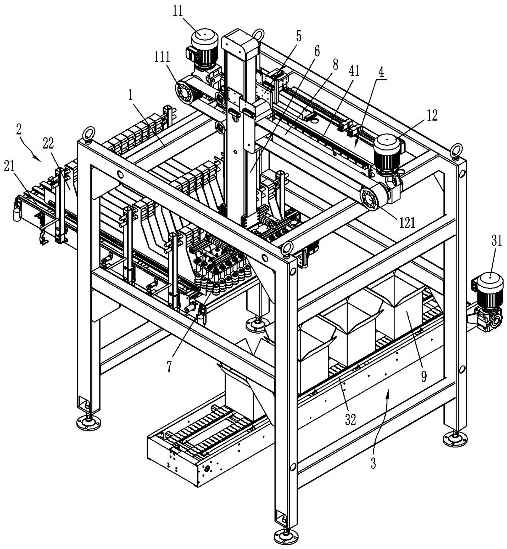
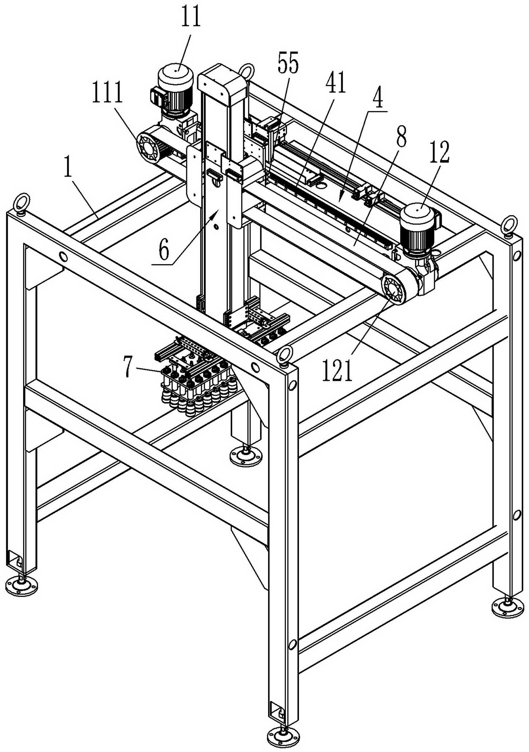
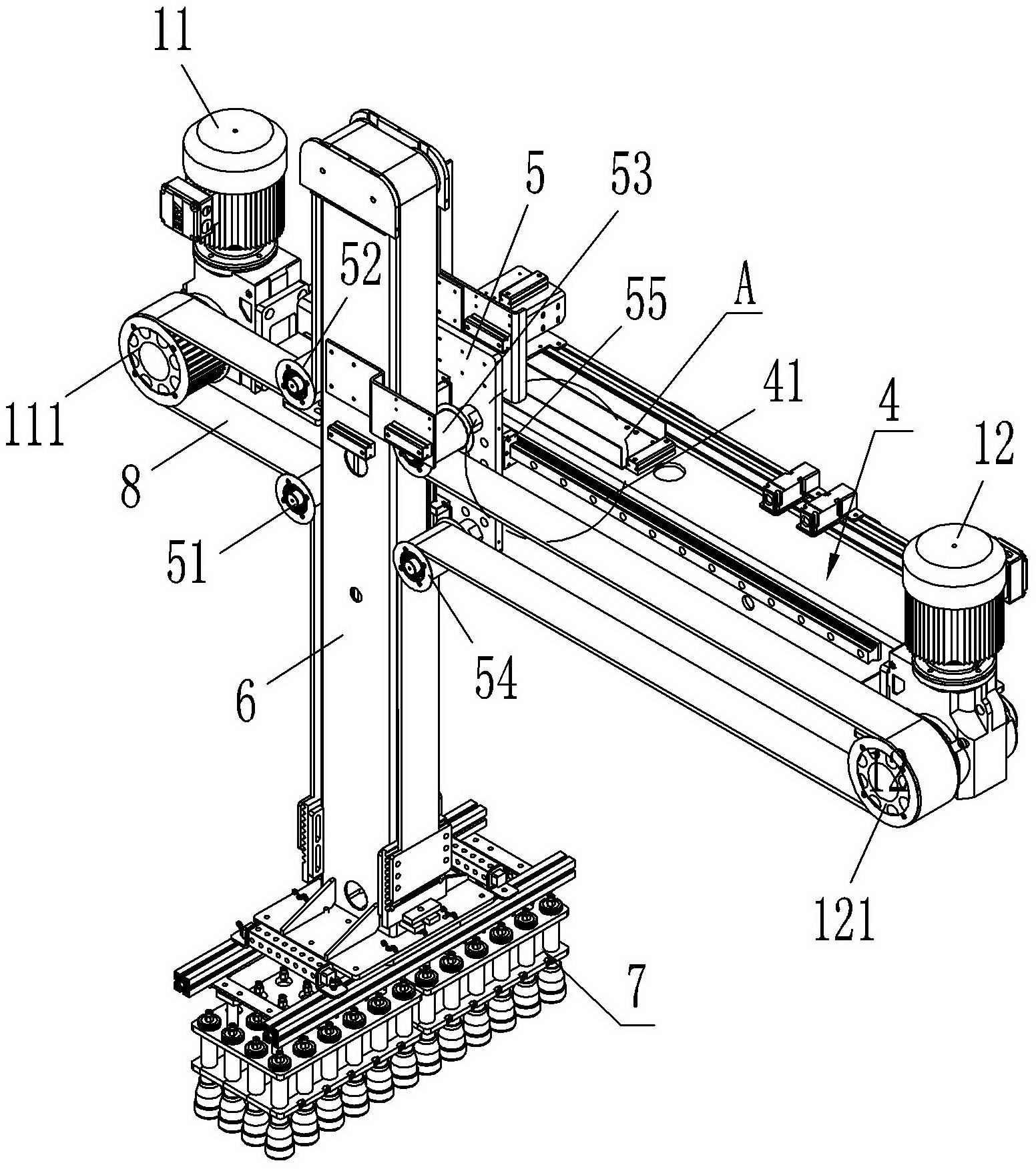
[0015] Such as Figures 1 to 8 As shown, a kind of packing machine of the present invention comprises frame 1, and the bottom of frame 1 has bottle conveying device 2 and case conveying device 3, and this bottle conveying device 2 and conveying case device 3 are prior art , wherein, the bottle conveying device 2 mainly includes a bottle conveying belt 21 driven by a motor (not shown in the figure) for conveying bottles, and a bottle sorting mechanism 22 for sorting out the bottles conveyed by the bottle conveying belt 21. Case device 3 then mainly comprises motor 31, and is driven by motor 31, is used to transport case belt 32 to packing case 9, here no longer to the concrete structure of conveying bottle device 2 and case conveying device 3 and specific working principle To repeat, the top of the frame 1 is equipped with a translation frame 5 that can slide between the bottle conveying device 2 and the case conveying device 3, and the translation frame 5 is equipped with a li...


PUM


Abstract

The invention discloses a packing machine, which comprises a stander, wherein a bottle conveying device and a container conveying device are arranged below the stander; a translation frame capable of sliding between the bottle conveying device and the container conveying device is arranged on the upper part of the stander; a lifting frame capable of sliding up and down along the translation frame is arranged on the translation frame; a bottle catching component is arranged at the lower end of the lifting frame; a first servo motor and a second servo motor are arranged at a position, corresponding to the translation frame, on the stander; a first guide pinch roller, a second guide pinch roller, a third guide pinch roller and a fourth guide pinch roller are arranged on the translation frame; and after a transmission device moves around the first guide pinch roller, a synchronizing wheel of the first servo motor, a second guide pinch roller, a guide wheel arranged at the upper end of the lifting frame, the third guide pinch roller, a synchronizing wheel of the second servo motor and the fourth guide pinch roller, two ends of the transmission device are fixed on the lower part of the lifting frame. The packing machine has a simple structure; a moving trace of the packing machine can be finished according to any assumed realizable curve trace; furthermore, the packing machine is stable in performance, high in working efficiency and low in electrical load.

Description

technical field [0001] The invention relates to a packing machine for packing bottled products into packing cases. Background technique [0002] After PET bottles, glass bottles, cans and other bottled products are filled, they often need to be packed into packing boxes for transportation and storage management. The most traditional packing work is done manually, but manual packing is inefficient and labor-intensive. The shortcomings such as high strength are far from meeting the requirements of automated production. In order to improve efficiency, the existing technology often uses mechanical traditional box packing machines or robots to carry out box packing work, but the existing traditional box packing machines have complex structures and inconvenient operations. , difficult maintenance and other shortcomings, and the high cost of the robot packing machine still cannot meet the production requirements. [0003] The Chinese patent No. "ZL 200920052063.6" discloses a tran...

Claims


Application Information

Patent Timeline
Patent Type & Authority Applications(China)
IPC IPC(8): B65B21/12B65B65/02
Inventor 曾国友邓凌
Owner GUANGZHOU TECH LONG PACKAGING MACHINERY CO LTD
Why Eureka
Try Eureka