
Heat dissipation hydraulic cylinder

A hydraulic cylinder and cooling fin technology, applied in the field of hydraulic cylinders, can solve problems such as sealing ring aging, heat accumulation, and heat dissipation difficulties, and achieve the effects of simple production and processing, improved service life, and good heat dissipation effect

Inactive Publication Date: 2016-07-20
天津峰盛工贸发展有限公司
View PDF0 Cites 4 Cited by
  • Summary
  • Abstract
  • Description
  • Claims
  • Application Information

AI Technical Summary

Problems solved by technology

[0002] The heating of the hydraulic system is a major problem in the hydraulic system. To solve this problem, a radiator is often installed in the circuit of the hydraulic system to cool the hydraulic oil to achieve the purpose of cooling the entire system. However, in the hydraulic cylinder, the piston and the cylinder block The largest heat source caused by the back and forth friction of the contact surface. Due to the tight contact surface, the hydraulic oil cannot enter it, resulting in difficulty in heat dissipation and heat accumulation. The rise of heat will cause the aging of the sealing ring and the accelerated wear of the piston.
The complex structure of the existing heat dissipation oil cylinder heat dissipation device brings difficulties to the production and processing of the oil cylinder, and the heat dissipation effect is not good

Method used


Image

  • Heat dissipation hydraulic cylinder

Examples


Embodiment Construction

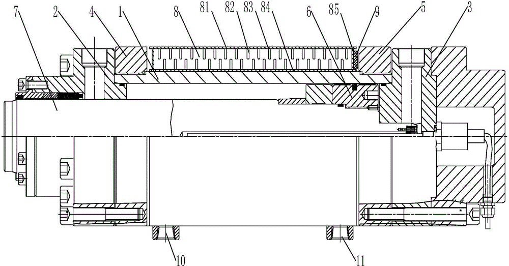
[0015] A heat dissipation hydraulic cylinder, comprising a cylinder body 1, a cylinder head 2, a cylinder bottom 3, a front flange 4, a rear flange 5, a piston 6, and a piston rod 7; the front flange 4 and the rear flange on the outer side of the cylinder body 1 5 are provided with a cooling device 8 and a temperature sensing device 9, the temperature sensing device 9 is arranged on the cooling device 8, the cooling device 8 includes a cooling ring 81 and a cooling fin 82 inside the cooling ring 81, and the cooling ring 81 includes The inner ring 83, the outer ring 84, the side wall 85, the water inlet 10 and the water outlet 11, and the cooling fins 82 are respectively arranged on the inner side of the inner ring 83 and the inner side of the outer ring 84 and arranged in a staggered manner, and the water inlet 10 and the water outlet 11 are arranged on the outer ring 84 outside.

[0016] The temperature sensing device 9 includes a temperature measuring device and a temperatur...


PUM


Abstract

The invention provides a heat dissipation hydraulic cylinder. The heat dissipation hydraulic cylinder comprises a cylinder body, a cylinder head, a cylinder bottom, a front flange, a rear flange, a piston and a piston rod. A heat dissipation device and a temperature sensing device are arranged on the portion, between the front flange and the rear flange, of the outer side of the cylinder body. The temperature sensing device is arranged on the heat dissipation device. The heat dissipation device comprises a cooling ring and cooling fins located in the cooling ring. The cooling ring comprises an inner ring, an outer ring, a side wall, a water inlet and a water outlet. The cooling fins are arranged on the inner side of the inner ring and the inner side of the outer ring in a staggered mode. The water inlet and the water outlet are formed in the outer side of the outer ring. After the heat dissipation device is installed, the overall dimension of the hydraulic cylinder is not increased, and no additional space is occupied. Production and machining are easy, installation is convenient, the heat dissipation effect is good, an operator can know the temperature of hydraulic oil in the hydraulic cylinder at any time, and the service life of the hydraulic cylinder is prolonged.

Description

technical field [0001] The invention relates to a hydraulic cylinder, in particular to a heat dissipation hydraulic cylinder. Background technique [0002] The heating of the hydraulic system is a major problem in the hydraulic system. To solve this problem, a radiator is often installed in the circuit of the hydraulic system to cool the hydraulic oil to achieve the purpose of cooling the entire system. However, in the hydraulic cylinder, the piston and the cylinder block The largest heat source caused by the back and forth friction of the contact surface. Due to the tight contact surface, the hydraulic oil cannot enter it, resulting in difficulty in heat dissipation and heat accumulation. The increase in heat will cause the aging of the sealing ring and the accelerated wear of the piston. The structure of the existing heat dissipation oil cylinder heat dissipation device is complicated, which brings difficulties to the production and processing of the oil cylinder, and the ...

Claims


Application Information

Patent Timeline
Patent Type & Authority Applications(China)
IPC IPC(8): F15B15/14F15B21/04
Inventor 刘砚俊
Owner 天津峰盛工贸发展有限公司
Learn More