Stereoscopic display device
A technology of a stereoscopic display device and a display panel, which is applied in optics, instruments, nonlinear optics, etc., can solve problems such as crosstalk and large optical path fluctuations, and achieve the effects of improving the degree of deflection, enhancing the effect, and reducing the phenomenon of crosstalk
- Summary
- Abstract
- Description
- Claims
- Application Information
AI Technical Summary
Problems solved by technology
Method used
Image
Examples
Embodiment 1
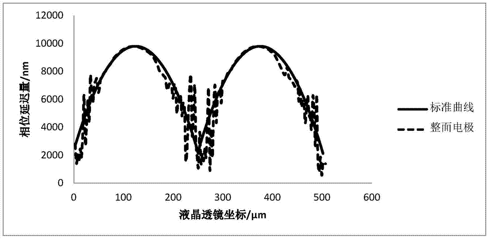
[0046] like Figure 4 and Figure 7 As shown, the display panel 1 is a 5.5-inch, 720p (eg, 1280×720 pixels) liquid crystal panel. The first electrode 24 is placed at an angle of 75° to the left relative to the horizontal direction, the width of the liquid crystal lens unit is equal to 0.256mm, and the cell thickness of the liquid crystal lens 2 is 0.030mm, and the ordinary light refractive index n of the liquid crystal molecule 23 is o is 1.524, extraordinary light refractive index n e is 1.824. Since the display unit 11 of the display panel 1 includes three display subunits 111 , it can be obtained that the width of each display subunit 111 is about 31 μm. The width of the first electrodes 24 is set to be 15 μm, the distance between two adjacent first electrodes 24 is 17 μm, and the second electrodes 25 are surface electrodes.
[0047] Similarly, the voltage applied to the first electrode 24 at the boundary of the liquid crystal lens unit is the largest and greater than t...
Embodiment 2
[0052] like Figure 11 As shown, the display panel 1b is a 5.5-inch liquid crystal panel with a resolution of 2K (eg, 2048×1080 pixels). Each liquid crystal lens unit of the liquid crystal lens is placed obliquely to the right by 75° with respect to the horizontal direction of the display panel 1b, and the width of the liquid crystal lens units, that is, the pitch, is equal to 18 μm. Since the display unit of the display panel 1b includes three display subunits 111b, it can be obtained that the width of each display subunit 111b is about 15 μm. In this way, the width of the first electrodes 24 b is 15 μm, the distance between two adjacent first electrodes 24 b is 15 μm, and the second electrodes are surface electrodes.
[0053] Similarly, the voltage applied to the first electrode 24b at the boundary of the liquid crystal lens unit is the largest and greater than the threshold voltage v of the liquid crystal molecules th , the voltage applied from the corresponding first ele...
Embodiment 3
[0055] like Figure 12 As shown, the display panel 1c is a 28-inch liquid crystal panel with a resolution of 2K (eg, 2048×1080 pixels). The liquid crystal lens units of the liquid crystal lens are placed at an angle of 70° to the left relative to the horizontal direction of the display panel 1c, and the width of the liquid crystal lens units, that is, the pitch, is equal to 33 μm. Since the display unit of the display panel 1c includes three display subunits 111c, it can be obtained that the width of each display subunit 111c is about 57 μm. In this way, the width of the two first electrodes 24c located at the boundary of the liquid crystal lens unit is 15 μm, the width of other first electrodes 24c in the middle of the first electrodes 24c on both sides of the liquid crystal lens unit is 20 μm, and the adjacent two first electrodes 24c The distance between them is 30 μm, and the second electrode is a surface electrode.
[0056] Similarly, the voltage applied to the first el...
PUM
| Property | Measurement | Unit |
|---|---|---|
| thickness | aaaaa | aaaaa |
| refractive index | aaaaa | aaaaa |
| refractive index | aaaaa | aaaaa |
Abstract
Description
Claims
Application Information
 - R&D
- Intellectual Property
- Life Sciences
- Materials
- Tech Scout
- Unparalleled Data Quality
- Higher Quality Content
- 60% Fewer Hallucinations
Browse by: Latest US Patents, China's latest patents, Technical Efficacy Thesaurus, Application Domain, Technology Topic, Popular Technical Reports.
© 2025 PatSnap. All rights reserved.Legal|Privacy policy|Modern Slavery Act Transparency Statement|Sitemap|About US| Contact US: help@patsnap.com


