Reactor protection system two-out-of-three conforming maintenance bypass system

A reactor protection and maintenance bypass technology, which is applied in the fields of reactors, nuclear reactor monitoring, nuclear power generation, etc., can solve problems such as reducing the operability of the reactor

Active Publication Date: 2016-07-20
NUCLEAR POWER INSTITUTE OF CHINA
View PDF7 Cites 6 Cited by
  • Summary
  • Abstract
  • Description
  • Claims
  • Application Information

AI Technical Summary

Problems solved by technology

[0006] During the operation of the reactor, the unplanned shutdown caused by the failure of the safety monitoring device reduces the operability of the reactor. The behavior and measures of canceling one or more equipment functions in the protection system, that is, maintenance bypass. In the prior art, no relevant information has been found

Method used


Image

  • Reactor protection system two-out-of-three conforming maintenance bypass system
  • Reactor protection system two-out-of-three conforming maintenance bypass system
  • Reactor protection system two-out-of-three conforming maintenance bypass system

Examples


Embodiment 1

[0035] Such as Figure 1 to Figure 5 shown.

[0036] Two of the three reactor protection systems are in line with the maintenance bypass system,

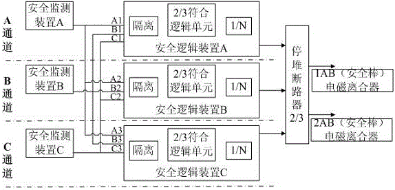
[0037] Including the reactor protection system, the reactor protection system includes a safety monitoring device A located in channel A, a safety monitoring device B located in channel B, a safety monitoring device C located in channel C, and a safety logic device A located in channel A , Safety logic device B located in channel B, safety logic device C located in channel C, safety monitoring device A outputs protection signal A1, protection signal A2, protection signal A3, safety monitoring device B outputs protection signal B1, protection Signal B2, protection signal B3, safety monitoring device C outputs protection signal C1, protection signal C2, protection signal C3, safety logic device A receives protection signal A1, protection signal B1, protection signal C1, safety logic device B receives protection signal A2 , protectio...

Embodiment 2

[0050] Such as Figure 5 shown.

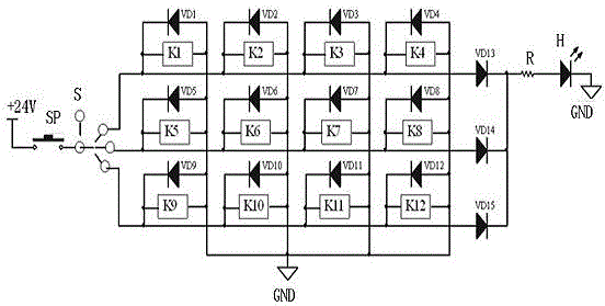
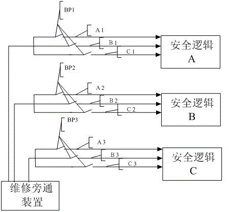
[0051] On the basis of Embodiment 1, preferably, since the selection of the bypass signal contact in the above system is random, there are two signal contacts on the output circuit of the same relay selected in the implementation. After the points are gathered, the bypass signal contact is formed. Therefore, if the relay fails, the output circuit of the relay cannot be closed, so the above two signal contacts will not be grounded, so bypass processing cannot be performed. At this time, the bypass system is unreliable. Therefore, in order to avoid the occurrence of the above-mentioned situation, the present invention adopts the following circuit setting scheme, that is, select a signal contact in the output circuit of any relay, and then select a contact in the output circuit of another relay, and connect the two signals The contacts are collected to form a bypass signal contact. After this setting, the purpose of increasing the stability of ...


PUM


Abstract

The invention discloses a reactor protection system two-out-of-three conforming maintenance bypass system, comprising a reactor protection system and a 2/3 conforming logic bypass unit, wherein the 2/3 conforming logic bypass unit comprises a rotary switch S which is provided with four gear contactors and also comprises twelve relays which are all normally open relays. Every four relays of the twelve relays are seen as one group; input ends of input circuits of the four relays of the first group are all connected to first gear contactors, input ends of input circuits of the four relays of the second group are all connected to second gear contactors, and input ends of input circuits of the four relays of the third group are all connected to third gear contactors. According to the system, a bypass device is arranged between a safety monitoring device and a safety logic device so that the protection system maintenance bypass function is added. Device on-line maintenance and test can be achieved; non-planned reactor shutdown probability due to device fault is reduced; the performability of reactors is increased; and production efficiency is guaranteed.

Description

technical field [0001] The invention relates to a safety control technology of a reactor protection system, in particular to a two-out-of-three coincidence maintenance bypass system of the reactor protection system. Background technique [0002] The overall upper 2 / 3 (two out of three) channel combination of the emergency shutdown unit of the reactor protection system, each safety logic channel combination adopts a partial 2 / 3 conforming structure, composed of a three-channel safety logic device and an emergency shutdown circuit breaker The multi-channel overall 2 / 3 conforms to the structure. [0003] The signals monitored by the safety monitoring device are composed of 24 protection input signals of four signal types: nuclear measurement parameters, process measurement parameters, protection system equipment status and system power supply status. The 24 kinds of protection signals sent to the safety logic device are composed of two partial coincidence modes of "2 / 3 logic c...

Claims


Application Information

Patent Timeline
Patent Type & Authority Applications(China)
IPC IPC(8): G21D3/04G21C17/00
CPCG21C17/00G21D3/04Y02E30/00Y02E30/30
Inventor 武文超李林洪李普葛源李子彦邹德光陈启兵邱卫东杨先军陆星
Owner NUCLEAR POWER INSTITUTE OF CHINA
Why Eureka
Try Eureka