
Copper wire pay-off device

A wire payoff, copper wire technology, applied in electrical components, circuits, cable/conductor manufacturing, etc., can solve the problems of copper wire breakage, economic loss, reel wall collision or friction, etc., to avoid contact and reduce wear and tear Volume, easy to get off the roll effect

Inactive Publication Date: 2016-07-20
CHENGDU XINGDA OF COPPER CO LTD
View PDF3 Cites 2 Cited by
  • Summary
  • Abstract
  • Description
  • Claims
  • Application Information

AI Technical Summary

Problems solved by technology

[0003] In the process of copper stranded wire processing, that is, in the copper wire stranding process, the turns of copper wire are drawn and twisted together in a certain direction and according to certain rules to form a whole twisted core, but the copper When the wire is removed from the drum, it is easy to collide or rub against the wall of the drum, and even cause the copper wire to break in severe cases, resulting in large economic losses

Method used


Image

  • Copper wire pay-off device
  • Copper wire pay-off device
  • Copper wire pay-off device

Examples


Embodiment 1

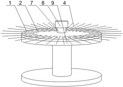
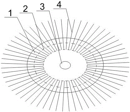
[0028] Such as Figure 1~Figure 5 As shown, this embodiment includes a reel 9, a brush plate 1 and a plurality of thin resin lines 4, and a fixing hole 3 is opened in the middle of the brush plate 1, and a plurality of thin resin lines 4 are arranged along the brush plate 1. The radial direction of the brush plate 1 extends outward, and the upper surface of the brush plate 1 is bonded with a concentric and annular lower pressure plate 2, the lower pressure plate 2 partially covers the resin thin line 4, and The lower surface of the lower pressing plate 2 is provided with an annular groove 5, and a curved section 6 is arranged on the plurality of thin resin wires 4, and the curved section 6 is placed in the annular groove 5, and on the upper end surface of the drum 9 The middle part is provided with a positioning rod 7, and the positioning rod 7 runs through the fixing hole 3, and there are guide grooves 10 with a circular arc-shaped cross section on both sides of the positioni...


PUM


Abstract

A copper wire pay-off device disclosed by the present invention comprises a brush plate and a plurality of resin fine wires, a fixing hole is arranged in the middle part of the brush plate, and the plurality of resin fine wires extend outwards along the radial direction of the brush plate. A concentric and annular lower platen is adhered on the upper surface of the brush plate, the resin fine wires are covered by the lower platen locally, and the lower surface of the lower platen is equipped with an annular groove in which a bending segment is placed. According to the present invention, by utilizing the flexibility of the plurality of resin fine wires on the brush plate and extending outwards, a copper wire is contacted with the resin fine wires directly before breaking away from a drum, so that the operation amplitude of the copper wire is increased when the copper wire breaks away from the drum, the resin fine wires recover to the initial positions because of the own elastic deformation recovery effects after generating a certain swing upwards along with the copper wire, at the same time, the wear extent caused by the contact of the copper wire and the resin fine wires can be neglected, namely, the wear of the copper wire is reduced while the copper wire can break away from the drum conveniently and rapidly.

Description

technical field [0001] The invention relates to the field of copper stranded wire processing, in particular to a copper wire pay-off device. Background technique [0002] The twisting principle of the copper stranded wire is as follows. When the copper wire passes through the twisting bow on the twisting machine, the twisting bow passes through the circular motion, so that the individual copper wires are helically wound together, and the twisted copper wire is a single copper wire. Where the maximum amount of wire is used, copper wires of different specifications and different numbers are twisted together in a certain order and lay length to become a conductor with a larger diameter. The copper wire is soft, and the wires processed by it have better bending performance. [0003] In the process of copper stranded wire processing, that is, in the copper wire stranding process, the turns of copper wire are drawn and twisted together in a certain direction and according to cert...

Claims


Application Information

Patent Timeline
Patent Type & Authority Applications(China)
IPC IPC(8): H01B13/02B65H75/18
CPCH01B13/0207B65H75/18B65H2701/50
Inventor 彭德均
Owner CHENGDU XINGDA OF COPPER CO LTD
Learn More