Eureka AIR delivers breakthrough ideas for toughest innovation challenges, trusted by R&D personnel around the world.

Switching control circuit, switching circuit and constant switching-on time control method

A technology of switch control circuit and logic control circuit, which is applied in the direction of control/regulation system, electrical components, and adjustment of electric variables, etc., which can solve the problems of slow dynamic response of current, low cost, and existence of minimum off time, so as to improve the transient state Response, extended off-time, effects of large voltage transitions

Active Publication Date: 2016-07-20
JOULWATT TECH INC LTD
View PDF4 Cites 13 Cited by
  • Summary
  • Abstract
  • Description
  • Claims
  • Application Information

AI Technical Summary

Problems solved by technology

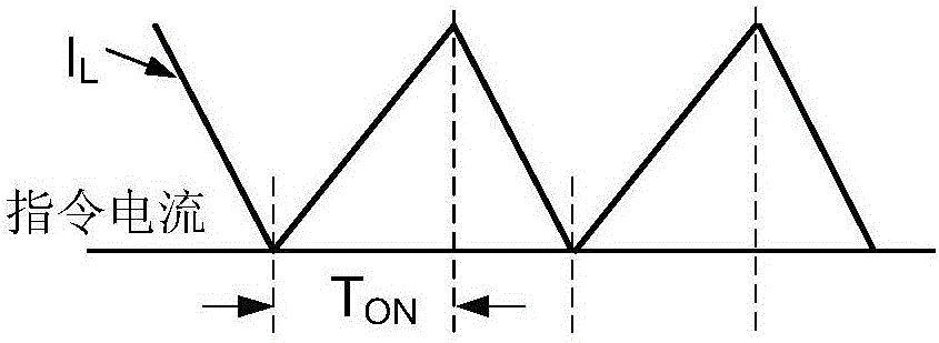
[0004] The traditional solution has the advantages of relatively simple circuit, easy implementation, and relatively low cost, but mainly has the following disadvantages: 1. When the duty cycle is relatively large in constant on-time control, the current dynamic response is relatively slow (the inductor current cannot follow the command current), such as image 3 shown
2. In constant on-time control, due to the fixed on-time of the main switch and the minimum off-time, the maximum duty cycle of the switching circuit is limited

Method used


Image

  • Switching control circuit, switching circuit and constant switching-on time control method
  • Switching control circuit, switching circuit and constant switching-on time control method
  • Switching control circuit, switching circuit and constant switching-on time control method

Examples


Embodiment approach

[0049] As another implementation, the current detection circuit includes an inductor current sampling circuit, a fourth comparator, and a fifth comparator. The inductor current sampling circuit is coupled to the inductor of the switch main circuit, and is used to directly detect the magnitude of the inductor current instead of In the above method, the main current and the auxiliary current equal to the inductor current are detected. The positive input terminal of the fourth comparator is coupled to the output of the inductor current sampling circuit, the negative input terminal is coupled to the output of the third comparator U01 , and the output terminal is coupled to the input of the constant conduction logic control circuit. The positive input terminal of the fifth comparator is coupled to the output of the third comparator U01 , the negative input terminal is coupled to the output of the inductor current sampling circuit, and the output terminal is coupled to the input of t...


PUM


Abstract

The invention provides a switching control circuit, a switching circuit and a constant switching-on time control method. When switching-on time of a main pipe reaches constant switching-on time, whether inductive current reaches instruction current or not is detected; if the inductive current does not reach the instruction current, the switching-on time of the main pipe is prolonged; the main pipe is switched off and an auxiliary pipe is switched on after the inductive current reaches the instruction current or exceeds the instruction current by a certain threshold value; when the main pipe is switched off and the auxiliary pipe is switched on, whether the instruction current is lower than the instruction current or not is detected in real time; and if the auxiliary pipe is switched off, the main pipe is switched on again. The switching control circuit, the switching circuit and the constant switching-on time control method, provided by the invention, aim at realizing stable-voltage control of output voltage, so that the voltage conversion with a relatively large duty cycle is realized.

Description

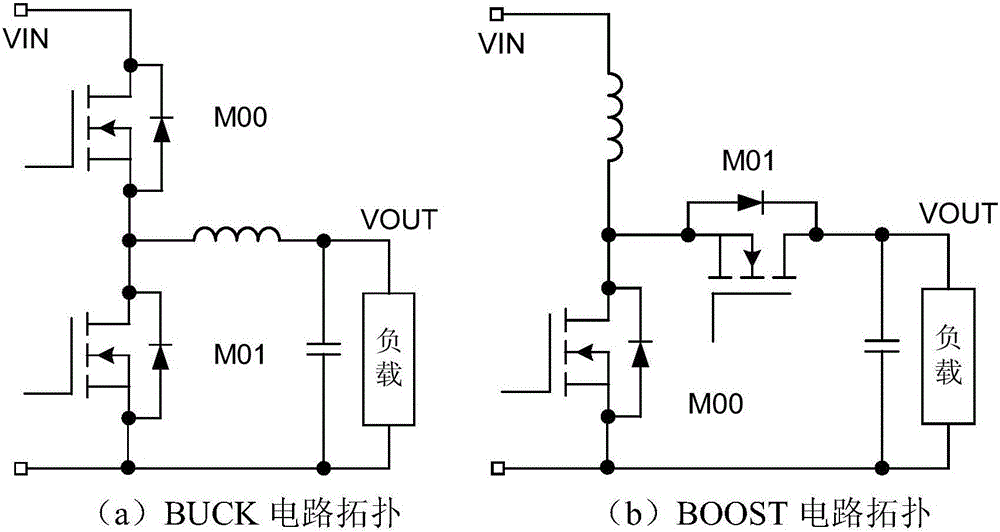
technical field [0001] The invention relates to the technical field, in particular to a switch control circuit, a switch circuit and a constant on-time control method. Background technique [0002] Such as figure 1 As shown, the traditional constant on-time (COT, Constant on time) control method realizes converting the input voltage into an output voltage to drive the load by controlling the main switch to be turned on for a constant time. In the step-down circuit (BUCK circuit) figure 1 In (a), the upper tube M00 is the main switching tube, and the lower tube M01 is the freewheeling diode or auxiliary switching tube; in the boost circuit (BOOST circuit) figure 1 In (b), the lower tube M01 is the main switching tube, and the upper tube M00 is the freewheeling diode or the auxiliary switching tube. [0003] In constant on-time control, after the main switch is turned on, the main switch is turned off after a constant time, at this time the freewheeling diode or auxiliary s...

Claims


Application Information

Patent Timeline
Patent Type & Authority Applications(China)
IPC IPC(8): H02M3/156
CPCH02M3/1563H02M1/0009H02M1/0096
Inventor 徐峰黄必亮任远程周逊伟
Owner JOULWATT TECH INC LTD
Why Eureka
Eureka Blog
Learn More