A switched capacitor high bandwidth envelope tracking power supply circuit and its control method

A switched-capacitor circuit, tracking power technology, applied in electrical components, output power conversion devices, conversion equipment without intermediate conversion to AC, etc. The problem of shortening the turn-off time can reduce the complexity and cost of the circuit, improve the switching performance and reliability, and extend the turn-on and turn-off time.

Active Publication Date: 2020-04-14
NANJING TECH UNIV
View PDF3 Cites 0 Cited by
  • Summary
  • Abstract
  • Description
  • Claims
  • Application Information

AI Technical Summary

Problems solved by technology

This increases the complexity and cost of the circuit, and reduces the system efficiency; on the other hand, since the ET power supply needs to track the envelope of the RF signal, its bandwidth is up to tens of MHz
When the switching converter directly tracks the reference signal with varying amplitude, its switching frequency often needs to reach 5 to 10 times the frequency of the reference signal, which makes it difficult to achieve high switching frequency.
At the same time, too high switching frequency will also shorten the turn-on and turn-off time of the switching device to several ns levels, the switching process is not sufficient, and even pulse loss occurs, which greatly reduces the system reliability and severely limits the tracking bandwidth of the ET power supply. improvement

Method used


Image

  • A switched capacitor high bandwidth envelope tracking power supply circuit and its control method
  • A switched capacitor high bandwidth envelope tracking power supply circuit and its control method
  • A switched capacitor high bandwidth envelope tracking power supply circuit and its control method

Examples


Embodiment 1

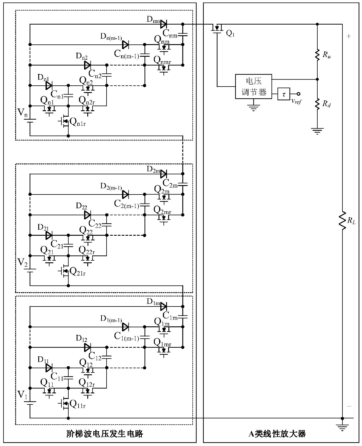
[0019] Example 1 reference figure 1 , a switched capacitor high-bandwidth envelope tracking power supply circuit, comprising a step wave voltage generating circuit and a class A linear amplifier, wherein the step wave voltage generating circuit is formed by connecting n switched capacitor circuits with the same structure in series;

[0020] where the nth switched capacitor circuit includes a power supply V n , the first-stage switched capacitor circuit unit, the second-stage switched capacitor circuit unit, ..., the m-1th stage switched capacitor circuit unit and the m-th stage switched capacitor circuit unit; the m-th stage switched capacitor circuit unit includes a main switch Tube Q nm , auxiliary switching tube Q nmr , Diode D nm and capacitance C nm , the main switch Q nm source, auxiliary switch Q nmr The drain and capacitor C nm One end of the diode D is connected to each other nm anode of the supply V n connected to the anode of the diode D nm The cathode and...

Embodiment 2

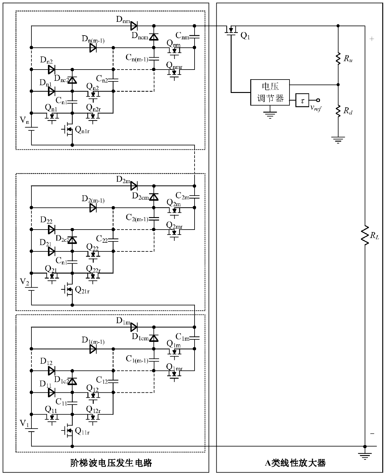
[0025] Example 2 reference figure 2 , on the basis of Embodiment 1, the Pth switched capacitor circuit is provided with a diode D ncP , the diode D nP The cathode and diode D ncP The cathode and the capacitor C nP The other end is connected; the diode D ncP The anode of the main switch Q nP The drain is connected; wherein, m>=P>=2, and P is an integer. Compared with Example 1, Example 2 can balance the charging and discharging time of each switching capacitor more.

[0026] figure 1 and figure 2 in, V 1 -V n stands for power, Q 11 -Q nm Represents the main switching tube, Q 11r -Q nmr Represents the auxiliary switching tube, D 11 -D nm Represents a diode, τ represents a delay circuit unit; the voltage regulator and the delay circuit unit are prior art, not described here, the power tube Q 1 Using a MOS tube or a triode, the voltage divider circuit unit is composed of a resistor R u and resistor R d formed in series, the resistor R u One end and power tube ...


PUM


Abstract

The invention discloses a switched capacitor type high-bandwidth envelope tracking power supply circuit, which includes a step wave voltage generating circuit and a class A linear amplifier, the step wave voltage generating circuit and the class A linear amplifier are connected in cascade, and the step wave voltage generating circuit The output is used as the input of a class A linear amplifier. The ladder wave voltage generating circuit is composed of n switched capacitor circuits with the same structure in series. The switching frequency of the switching tube in each switched capacitor circuit can achieve (1 / n):1 frequency reduction relative to the tracking signal frequency, and at the same time effectively expand The turn-on or turn-off time of the switch tube can be fully turned on or off to improve its working performance and reliability under high-bandwidth tracking conditions; compared with traditional methods, it can greatly reduce the number of power supplies and reduce the complexity of the circuit level and cost, and improve system efficiency.

Description

technical field [0001] The invention relates to a switched capacitor type high-bandwidth envelope tracking power supply, which is applied to wireless communication occasions. Background technique [0002] The development of mobile communication started from the first generation of mobile communication (1st Generation, 1G) commercially available in the late 1970s to the fourth generation of mobile communication (4th Generation, 4G) commercially available today, both in terms of modulation and information transmission Quantitatively, there has been a huge change. The first generation of mobile communication technology (1G) mainly uses analog cellular network technology, and the implementation methods include frequency division multiple access and carrier multiplexing. The second generation of mobile communication technology (2nd Generation, 2G) uses digital communication technology, through time division and code division multiple access technology to realize radio frequency ...

Claims


Application Information

Patent Timeline
Patent Type & Authority Patents(China)
IPC IPC(8): H02M3/07
CPCH02M3/07H02M1/0067
Inventor 郗焕刘宁徐永健曹娟朱颖
Owner NANJING TECH UNIV
Why Eureka
Try Eureka