Modified high-efficiency light-emitting diode (LED) drive circuit and drive method

A technology of LED drive and LED device, applied in the direction of electric lamp circuit layout, electric light source, electrical components, etc., can solve the problems of slow drop of input current, high input current, waste of energy, etc.

Active Publication Date: 2015-01-14
SILERGY SEMICON TECH (HANGZHOU) CO LTD
View PDF3 Cites 0 Cited by
  • Summary
  • Abstract
  • Description
  • Claims
  • Application Information

AI Technical Summary

Problems solved by technology

[0003] However, in this invention, abnormal load conditions, such as open circuit and short circuit, are not considered. When the load is open circuit, the voltage at the output terminal will become high instantaneously. At this time, if there is no overvoltage protection measure, it will cause waste of energy on the one hand, and on the other hand On the one hand, too high voltage is easy to

Method used


Image

  • Modified high-efficiency light-emitting diode (LED) drive circuit and drive method
  • Modified high-efficiency light-emitting diode (LED) drive circuit and drive method
  • Modified high-efficiency light-emitting diode (LED) drive circuit and drive method

Examples


Embodiment Construction

[0029] Several preferred embodiments of the present invention will be described in detail below with reference to the accompanying drawings, but the present invention is not limited to these embodiments. The present invention covers any alternatives, modifications, equivalent methods and schemes made on the spirit and scope of the present invention. In order to provide the public with a thorough understanding of the present invention, specific details are set forth in the following preferred embodiments of the present invention, but those skilled in the art can fully understand the present invention without the description of these details.

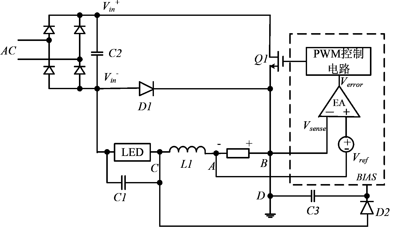
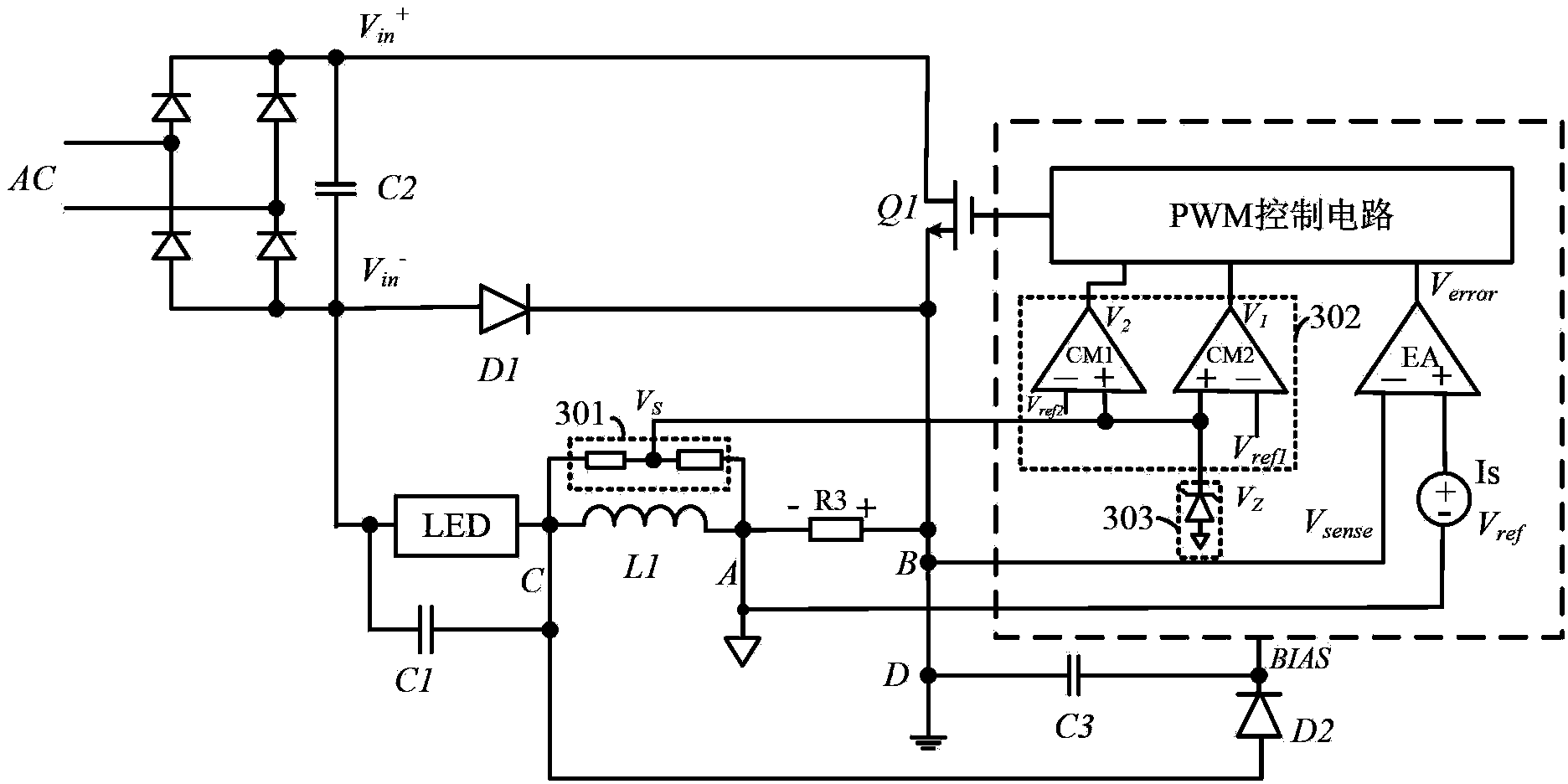
[0030] refer to image 3 , shows the circuit diagram of the first embodiment of an improved high-efficiency LED drive circuit according to the present invention; in this embodiment, the AC input power supply AC is converted into a DC power supply after passing through a rectifier bridge and a filter capacitor C2. The power switch tube Q1...


PUM


Abstract

In one embodiment, an LED driving circuit can include: (i) a sense circuit configured to sense an inductor voltage, and to generate a sense voltage signal; (ii) a protection control circuit configured to activate a first protection control signal in response to a comparison of the sense voltage signal against a first reference voltage to indicate an LED device is in a first load state; (iii) the protection control circuit being configured to activate a second protection control signal in response to a comparison of the sense voltage signal against a second reference voltage to indicate the LED device is in a second load state; and (iv) a PWM control circuit configured to control a power switch according to the first protection control signal or the second protection control signal, based on the load state of the LED device.

Description

technical field [0001] The invention relates to the technical field of power electronics, and more specifically, relates to an improved high-efficiency LED driving circuit and a driving method. Background technique [0002] With the widespread use of LED lighting, the status of LED driving power is also prominent. The matching of LED driving power directly affects the stability and safety of LED loads. However, in the design of LED driving power supply, it is still a major difficulty to make the driving power supply well matched with different control structures, and have good stability and high power utilization efficiency. The applicant of the present invention applied for a patent application for LED driving power supply in China, the title of which is "A high-efficiency LED driving circuit and driving method". The application was filed on January 10, 2011, and the application number is 201110005323.6 . The content published therein is incorporated herein as figure 1 a...

Claims


Application Information

Patent Timeline
IPC IPC(8): H05B37/02H05B44/00
CPCH05B33/0893Y02B20/346H05B33/0815Y02B20/341H05B45/58Y02B20/30H05B45/50H05B45/375H05B47/24
Inventor 陈伟
Owner SILERGY SEMICON TECH (HANGZHOU) CO LTD
Why Eureka
Try Eureka