Driving control circuit and method

A technology for driving control circuits and generating circuits, which is applied to electrical components, output power conversion devices, conversion of AC power input to DC power output, etc., can solve problems such as long startup time, power-off restart, etc. The effect of prolonging the off-time and prolonging the on-time

Pending Publication Date: 2017-08-22
JOULWATT TECH ZHANGJIAGANG INC LTD
View PDF3 Cites 0 Cited by
  • Summary
  • Abstract
  • Description
  • Claims
  • Application Information

AI Technical Summary

Problems solved by technology

[0005] In view of this, the purpose of the present invention is to provide a drive control circuit and method for realizing low

Method used


Image

  • Driving control circuit and method
  • Driving control circuit and method
  • Driving control circuit and method

Examples


Embodiment Construction

[0030] Preferred embodiments of the present invention will be described in detail below with reference to the accompanying drawings, but the present invention is not limited to these embodiments. The present invention covers any alternatives, modifications, equivalent methods and schemes made within the spirit and scope of the present invention.

[0031] In order to provide the public with a thorough understanding of the present invention, specific details are set forth in the following preferred embodiments of the present invention, but those skilled in the art can fully understand the present invention without the description of these details.

[0032] In the following paragraphs the invention is described more specifically by way of example with reference to the accompanying drawings. It should be noted that all the drawings are in simplified form and use inaccurate scales, which are only used to facilitate and clearly assist the purpose of illustrating the embodiments of t...


PUM


Abstract

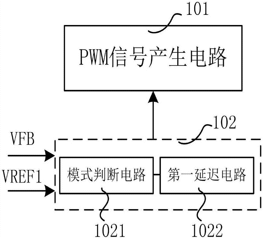
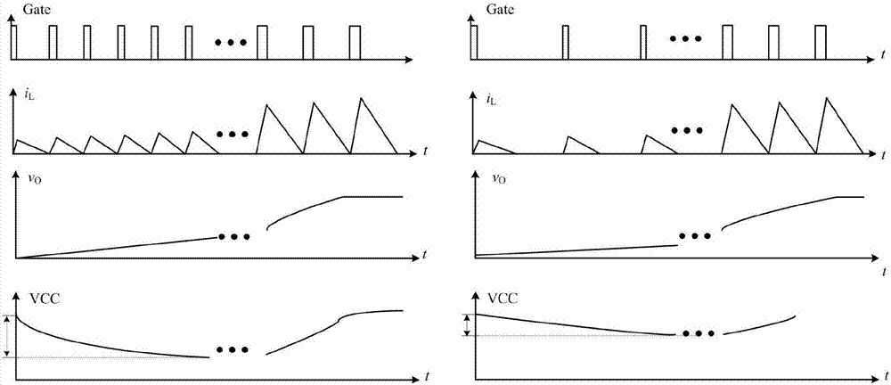
The invention discloses a driving control circuit and method. The power supply end of the driving control circuit is connected to a power supply circuit. In a start process, the driving control circuit is started when the voltage of the power supply end reaches starting voltage. The driving control circuit comprises a PWM signal generation circuit for generating a PWM signal used for determining turn-on time and turn-off time and used as a control signal for a switch; and an auxiliary start circuit for comparing, after the driving control circuit is started, a sampling signal representing the output voltage with first reference voltage, and entering an auxiliary start mode when the sampling signal is lower than the first reference signal. In the auxiliary start mode, the turn-off time represented by the PWM signal is prolonged to reduce switching frequency, or the turn-on time represented by the PWM signal is prolonged to increase an output voltage rise rate.

Description

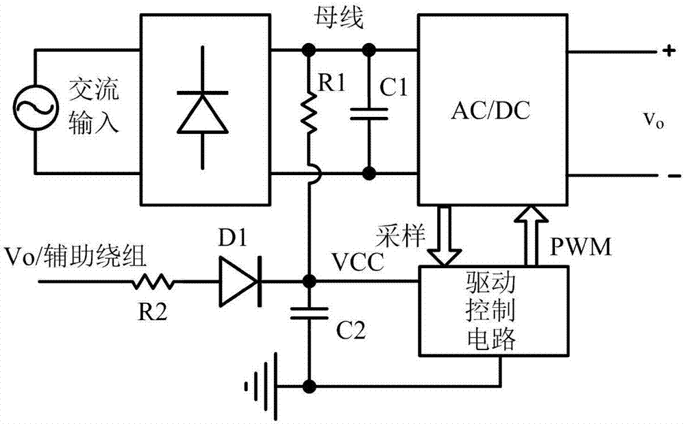
technical field [0001] The invention relates to the technical field of power electronics, in particular to a drive control circuit and method. Background technique [0002] Such as figure 1 As shown, for high PF (power factor) LED driver or constant voltage power supply, in order to reduce the system cost and improve the power supply efficiency and reliability of the control circuit during steady-state operation, the auxiliary winding of the inductor when the main power switch is turned off is generally used Or the output voltage supplies power to the control circuit. When initially powered on, because the control circuit has not obtained enough power supply voltage, it cannot drive the main power circuit to work normally. The common method is to add a limiter with a large resistance value between the input bus and the capacitor C2 at the power supply terminal VCC of the control circuit. When VCC is charged to the startup voltage (VCC_ON), ​​the circuit starts. [0003] I...

Claims


Application Information

Patent Timeline
IPC IPC(8): H02M1/36H02M7/217
CPCH02M1/36H02M7/2173
Inventor 查振旭刘国强任远程周逊伟
Owner JOULWATT TECH ZHANGJIAGANG INC LTD
Why Eureka
Try Eureka