Electro-hydraulic emergency turn-off system for testing process and control method

A technology of testing process and control method, which is applied in the field of oil and gas exploration and testing, can solve the problems of restricting the response time of the shutdown system, the difficulty of testing operation, and high risk, so as to strengthen the comprehensive safety control ability, improve reliability and interactivity , Improve the effect of control ability

Active Publication Date: 2021-06-25
CHINA SHIPPING APP OIL & GAS TESTING (TIANJIN) CO LTD
View PDF12 Cites 0 Cited by
  • Summary
  • Abstract
  • Description
  • Claims
  • Application Information

AI Technical Summary

Problems solved by technology

[0004] First, due to the influence of the number of cut-off points and the distance of the cut-off points, the pressure relief time of the pilot gas signal of the existing emergency shutdown system is long, which restricts the response time of the shutdown system, resulting in the shutdown time being generally 10s to 15s
[0005] Second, the nylon hose of the pilot signal is fragile and easy to leak. Once an accidental leakage or damage occurs, the controlled valve will not be able to open normally, resulting in the interruption of the operation. At the same time, it is difficult to confirm the leakage and correct it in the first place;
[0006] Third, it is difficult and risky to test high-temperature and high-pressure, high-yield gas wells, deep-water wells, and hydrogen sulfide wells. Once there is a high-pressure, high-yield fluid puncture and other dangerous situations, the leakage and diffusion of high-pressure fluid in the formation is very fast, and it takes 10 to 15 seconds. The shutdown response time cannot guarantee the safety requirements of the operation;
[0007] Fourth, the existing test emergency shutdown system cannot be incorporated into the shutdown system of the platform, and cannot meet the needs of high-end platform security integration

Method used


Image

  • Electro-hydraulic emergency turn-off system for testing process and control method
  • Electro-hydraulic emergency turn-off system for testing process and control method
  • Electro-hydraulic emergency turn-off system for testing process and control method

Examples


Embodiment Construction

[0059] The present invention will be further described in detail below in conjunction with the accompanying drawings, so that those skilled in the art can implement it with reference to the description.

[0060] Different from the traditional control system that uses compressed air as the control signal, the present invention uses current as the control signal and carries out control logic design. It is a set of ground testing process emergency shutdown system and its control method, which is an emergency shutdown system for oil and gas well testing ground process. Shutdown provides a new means of control.

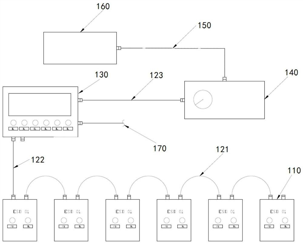
[0061] Such as figure 1As shown, the present invention provides an electro-hydraulic emergency shutdown system for testing procedures, including: a plurality of remote control button boxes 110, a first multi-core cable 121, a second multi-core cable 122, a third multi-core cable Cable 123, electric control panel 130, solenoid valve box 140, induction gas pipeline 150, hyd...


PUM


Abstract

The invention discloses an electro-hydraulic emergency turn-off system for a test process. The system comprises a plurality of remote control button boxes which are connected in parallel through a multi-core cable, an electric control panel which is connected with the plurality of remote control button boxes, and is provided with a data communication interface, an electromagnetic valve box which is connected with the electric control panel, an induction gas pipeline and a hydraulic control panel, wherein one end of the induction gas pipeline is connected with the electromagnetic valve box; and the hydraulic control panel is connected with the other end of the induction gas pipeline. The invention further discloses a control method of the electro-hydraulic emergency turn-off system for testing the process, the electro-hydraulic emergency turn-off system is controlled through bus control or signal input so that the ground test process is isolated from a test shaft, and the response time of the turn-off system is shortened in an electric signal control mode.

Description

technical field [0001] The invention relates to the technical field of oil and natural gas exploration and testing, and more specifically, the invention relates to an electro-hydraulic emergency shutdown system and a control method for a testing process. Background technique [0002] At present, the emergency shutdown system commonly used during offshore oilfield testing uses compressed air as the pilot signal. When an emergency occurs, pull the ESD button to open the pressure relief valve, and the pilot gas releases pressure to activate the hydraulic control panel to control the ground test tree or ground safety. The hydraulic control valve of the valve is closed to realize the emergency shutdown of the ground test process. The ESD button is connected to the hydraulic control panel through several tens of meters of pilot signal gas pipelines, and the hydraulic control panel is controlled. The length of the pilot signal gas pipeline directly affects the shutdown time. [00...

Claims


Application Information

Patent Timeline
Patent Type & Authority Applications(China)
IPC IPC(8): G05B23/02
CPCG05B23/0262G05B2219/24065
Inventor 魏剑飞陈光峰田向东冯一白通洲宋斌
Owner CHINA SHIPPING APP OIL & GAS TESTING (TIANJIN) CO LTD
Why Eureka
Try Eureka