Check patentability & draft patents in minutes with Patsnap Eureka AI!

Clock Synchronization Method of Distributed Nodes in Network System

A network system and clock synchronization technology, which is applied in transmission systems, synchronization devices, data exchange networks, etc., can solve problems such as clock differences, strong real-time performance, and inconsistent node clock characteristics

Inactive Publication Date: 2018-09-14
EAST CHINA JIAOTONG UNIVERSITY
View PDF5 Cites 0 Cited by
  • Summary
  • Abstract
  • Description
  • Claims
  • Application Information

AI Technical Summary

Problems solved by technology

[0002] The existing clock synchronization method mainly consists of the IEEE1588 clock synchronization method. In this method, each synchronization process requires three data communications between the reference node and the synchronization node to determine the network transmission delay, unknown parameters such as data sending and receiving delays, and calculate The process takes a long time; and due to the need to reciprocate data request and transmission during the synchronization process, the real-time performance of clock synchronization is reduced. Not only that, the existing clock synchronization method defaults to the same clock characteristics of each node in the distributed system. The starting time of each node in the system is inconsistent, resulting in the clock difference of each node in the system. In fact, in the distributed system, not only the starting time of each node's clock is inconsistent, but also the clock characteristics of each node are also inconsistent.
[0003] IEEE1588 has certain applicability in some occasions that do not require high real-time performance, but in industrial automation and occasions that require high real-time performance, it cannot meet the requirements of small amount of calculation and strong real-time performance during the synchronization process.

Method used


Image

  • Clock Synchronization Method of Distributed Nodes in Network System

Examples


Embodiment Construction

[0022] Attached below figure 1 The present invention will be further described with specific examples.

[0023] The present invention provides a clock synchronization method for distributed nodes in a network system, comprising the following steps:

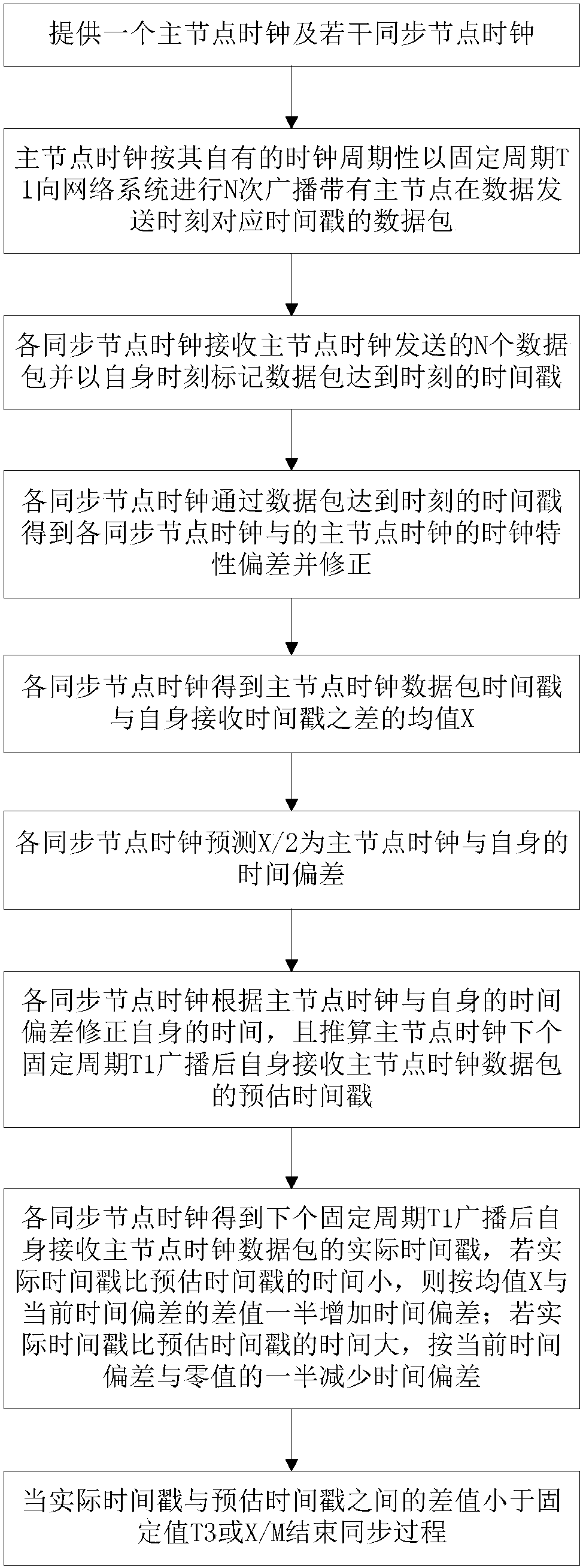
[0024] a. Provide a master node clock and several synchronous node clocks;

[0025] b. The clock of the master node broadcasts to the network system N times the data packet with the time stamp corresponding to the time when the data is sent by the master node with a fixed period T1 according to its own clock cycle;

[0026] c. Each synchronization node clock receives N data packets sent by the master node clock and marks the time stamp of the arrival time of the data packets with its own time;

[0027] d. Each synchronization node clock obtains the clock characteristic deviation between each synchronization node clock and the master node clock through the time stamp of the arrival time of the data packet;

[0028] e. Each synch...


PUM


Abstract

The invention discloses a method for synchronizing clocks of distributed nodes in a network system, and aims to provide a method for synchronizing node clocks in a network system quickly and accurately. The clock characteristic deviation between the clock of the synchronization node and the clock of the master node, and the clock frequency of each synchronization node clock in a fixed period is corrected to the clock frequency of the master node clock through the deviation, and X is predicted by the clock of each synchronization node. The estimated initial value is obtained from the time deviation of the master node clock, and the estimated time stamp of the master node clock data packet received by itself after the next fixed period T1 broadcast of the master node clock is calculated based on the time deviation, and it is quickly predicted and compared with the master node clock and the clocks of each synchronization node. The estimated time stamp and the actual time stamp can quickly synchronize the synchronization node clock of the network system.

Description

technical field [0001] The invention relates to a precise clock synchronization method, more specifically to a distributed node clock synchronization method in a network system. Background technique [0002] The existing clock synchronization method mainly consists of the IEEE1588 clock synchronization method. In this method, each synchronization process requires three data communications between the reference node and the synchronization node to determine the network transmission delay, unknown parameters such as data sending and receiving delays, and calculate The process takes a long time; and due to the need to reciprocate data request and transmission during the synchronization process, the real-time performance of clock synchronization is reduced. Not only that, the existing clock synchronization method defaults to the same clock characteristics of each node in the distributed system. The starting time of each node in the system is inconsistent, which leads to the diff...

Claims


Application Information

Patent Timeline
Patent Type & Authority Patents(China)
IPC IPC(8): H04L7/00H04L12/26H04J3/06
CPCH04J3/0661H04L7/0016H04L43/106
Inventor 陈鹏展杨辉刘曦茹岩张欣杨希于庆庆
Owner EAST CHINA JIAOTONG UNIVERSITY
Features
  • R&D
  • Intellectual Property
  • Life Sciences
  • Materials
  • Tech Scout
  • Unparalleled Data Quality
  • Higher Quality Content
  • 60% Fewer Hallucinations
Learn More