Scalp clip output apparatus

A scalp clip and output device technology, which is used in wound clips, medical science, surgery, etc., can solve problems such as poor reliability and complex structure, and achieve the effects of reducing work intensity, improving surgical speed, and improving surgical quality.

Active Publication Date: 2016-07-27
河北诺盛科创生物科技有限公司
View PDF6 Cites 1 Cited by
  • Summary
  • Abstract
  • Description
  • Claims
  • Application Information

AI Technical Summary

Problems solved by technology

[0005] The technical problem to be solved by the present invention is to provide a scalp clip output device, which avoids the defects of complex structure and poor reliability

Method used


Image

  • Scalp clip output apparatus
  • Scalp clip output apparatus
  • Scalp clip output apparatus

Examples


Embodiment Construction

[0026] In order to make the object, technical solution and advantages of the present invention clearer, the present invention will be further described in detail below in conjunction with the accompanying drawings and embodiments. It should be understood that the specific embodiments described here are only used to explain the present invention, not to limit the present invention.

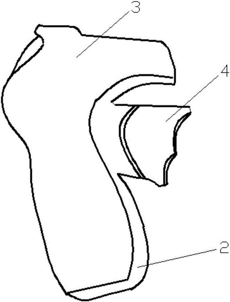
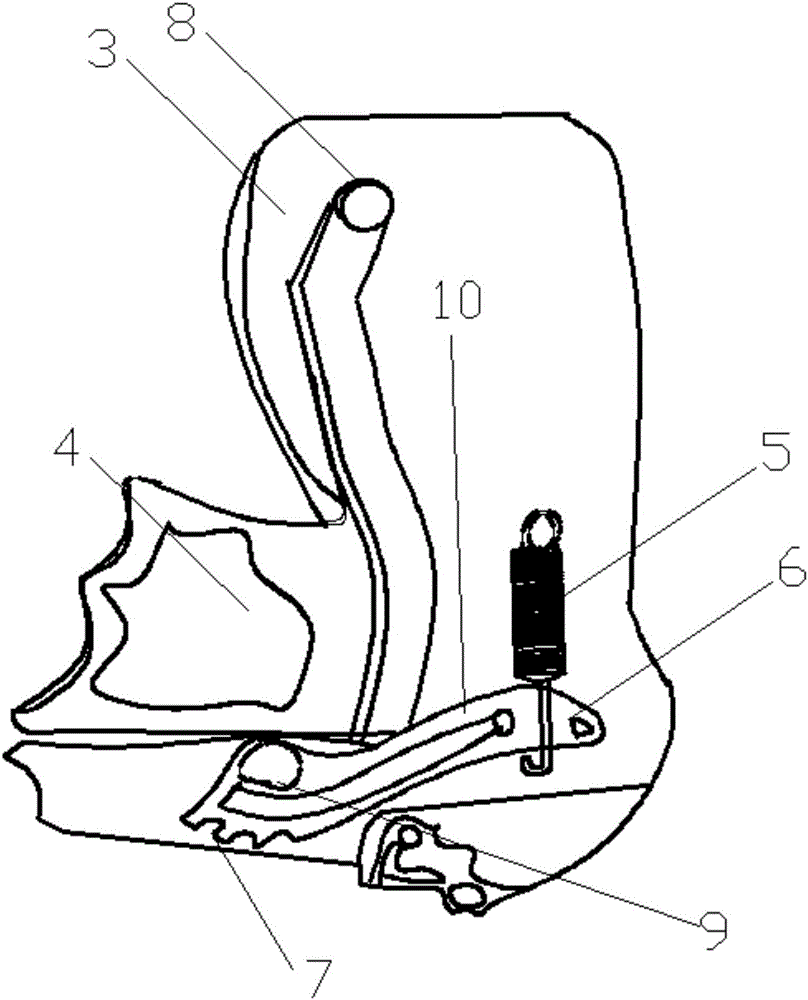
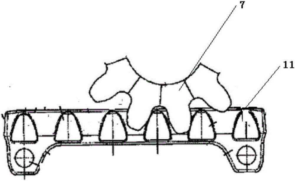
[0027] Such as Figure 1-Figure 10 As shown, the scalp wallet output device includes a gun chamber 1 and a gun body 2 fixed on the gun chamber 1, a driving system is arranged in the gun body 2, a sliding system is arranged in the gun chamber 1, and the gun body 2 is provided with a sliding system. The drive system and the sliding system are connected to form a linkage device.

[0028] The gun body 2 includes a gun casing 3 and a handle 4, the gun casing 3 is provided with a mechanical driving device, the handle 4 extends into the gun casing 3 and contacts with the mechanical driving device, and th...


PUM


Abstract

The invention discloses a scalp clip output apparatus which comprises a bore and a gun.The gun is fixed onto the bore, a driving system is arranged in the gun, a sliding system is arranged in the bore, and the driving system and the sliding system are connected with each other to form a linkage device.The scalp clip output apparatus has the advantage that shortcomings of complicated structures and poor reliability can be overcome by the aid of the scalp clip output apparatus.

Description

technical field [0001] The invention relates to the technical field of a scalp clip, in particular to a scalp clip output device. Background technique [0002] In the prior art, when performing brain surgery, it is necessary to use a large number of scalp clips to fix the cut scalp of the patient and to stop bleeding from the scalp, and the scalp clips often include two clamping arms, two clamping arms One end of the arms is a jaw close to each other, and the other ends of the two clamping arms are connected by an elastic arc section. [0003] That is to say, the hemostasis of the scalp in craniocerebral surgery in the hospital is achieved by using a scalp clip. The function of the scalp clip is to fix the scalp tissue so that it does not separate from the skull and prevent it from bleeding. The scalp clip fixes the scalp tissue and does not separate from the skull tissue. The function of hemostasis and fixation facilitates the operation, thereby increasing the operation sp...

Claims


Application Information

Patent Timeline
IPC IPC(8): A61B17/128
CPCA61B17/1285A61B2017/00367A61B2017/12004
Inventor 李相均
Owner 河北诺盛科创生物科技有限公司
Why Eureka
Try Eureka