Power supply device for APM rapid transit system

A technology of power supply device and power supply rail, which is applied in the field of rail transit, can solve the problems of many power supply rails, rough power supply rail structure, large discharge and electromagnetic interference of the AC power supply system, and achieves low discharge and electromagnetic radiation interference, and saves engineering equipment costs. , the effect of low insulation protection requirements

Active Publication Date: 2016-07-27
CRRC PUZHEN BOMBARDIER TRANSPORTATION SYST CO LTD
View PDF6 Cites 6 Cited by
  • Summary
  • Abstract
  • Description
  • Claims
  • Application Information

AI Technical Summary

Problems solved by technology

[0003] Since the APM vehicle itself does not provide energy, it is necessary to continue laying power supply devices to ensure the continuous operation of the vehicle. At present, the domestic Beijing T3 terminal building and the APM in Guangzhou adopt a 600V three-phase AC 5-rail power supply system (that is, A phase, B phase, C Phase three power supply rails, a ground rail and a signal rail), the power supply system is more complicated
In addition, the existing power supply rail has a rough structure and poor reliability, so it is urgent to solve this problem
[0004] Specifically, the existing APM in China adopts the 600V three-phase AC 5-rail power supply system. The power supply system includes A, B, and C three-phase three power supply rails, one ground rail and one signal rail. This type of power supply system Since the power supply adopts three-phase alternating current, many power supply rails are used, the production cost and floor area of ​​the project are relatively high, and the alternating current power supply system discharges and electromagnetic interference is large, so phase separation must be set, the reliability is relatively weak, and the power supply cannot be directly used by trains , the requirements for the car are relatively high

Method used


Image

  • Power supply device for APM rapid transit system
  • Power supply device for APM rapid transit system
  • Power supply device for APM rapid transit system

Examples


Embodiment Construction

[0029] The present invention will be further described below in conjunction with the accompanying drawings.

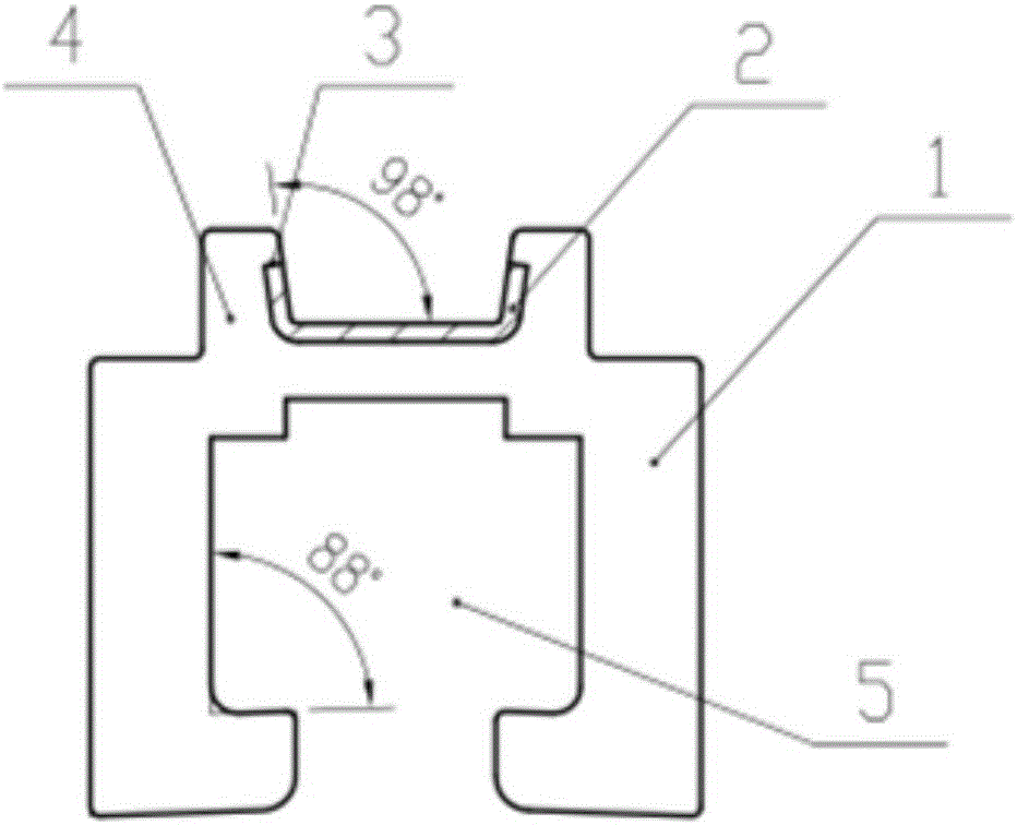
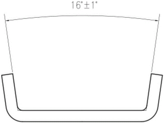
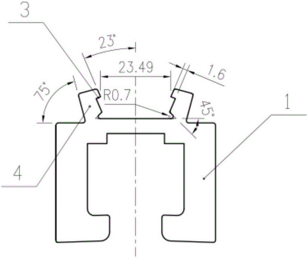
[0030] Such as Figures 1 to 7 As shown, the power supply device for the APM rapid transit system of the present invention includes a power supply rail device and a ground rail device, and the power supply rail device includes a power supply rail 21 and its accessories, and the power supply rail 21 is divided into a positive power supply rail 212 and a negative power supply rail 213 , the power supply rail device is connected to the positive and negative poles of the DC power supply system through a power feeder, and jointly provides continuous current receiving for the vehicle; the ground rail device includes a ground rail 22 and its accessories, and both the power supply rail device and the ground rail device include several anchor sections, Each anchor section is equipped with its own independent temperature compensation device, which is used to automatically compen...


PUM


Abstract

The invention discloses a power supply device for an APM rapid transit system. The power supply device comprises a power supply rail device and a grounded rail device. The power supply rail device comprises a power supply rail and an accessory thereof. The power supply rail comprises a positive pole power supply rail body and a negative pole power supply rail body. The power supply rail device is connected with a positive pole and a negative pole of a direct-current power supply system through power feeders, and continuous collecting currents are provided for a vehicle together. The grounded rail device comprises a grounded rail and an accessory thereof. The power supply rail device and the grounded rail device each comprise a plurality of anchoring sections, each anchoring section is provided with an independent temperature compensating device which is used for automatically compensating for the length expansion amount caused by environment temperature changes. According to the power supply device, two 750V direct-current power supply rail bodies are used for power supply, the grounded rail is grounded, the power supply mode of an APM is greatly simplified on the premise of meeting running requirements, the number of the power supply rail and the grounded rail is reduced, engineering equipment cost is reduced, and the occupied area is small; the equipment cost of the whole power supply device for the APM system is reduced on the premise of guaranteeing power supplied to a locomotive, the power supply utilization rate is increased, the power supply quality is improved, and the requirement for the structure of the locomotive is reduced.

Description

technical field [0001] The invention relates to the field of rail transit, in particular to a power supply device for an APM rapid transit system. Background technique [0002] The APM (Automated People Mover) rapid transit system is an automatic passenger rapid transit system installed to transport passengers between terminals. Its biggest feature is unmanned, electric power, rubber tires, and guide rails to drive on the concrete road. It can run in one carriage or connect several carriages together. This unmanned, fully automatic guided transportation system can provide high-quality services, and its one-way passenger capacity is between 20,000 and 25,000 passengers / h. It adopts fully enclosed lines, with small time intervals, responsiveness and precision. Sensitive than manual driving. Because its wheels are special rubber tires and use concrete passages, the running noise and vibration are greatly reduced, which improves the comfort of passengers. In addition, the veh...

Claims


Application Information

Patent Timeline
Patent Type & Authority Applications(China)
IPC IPC(8): B60M1/30
CPCB60M1/30
Inventor 赖锦堂高莹张国芳赵婷张娴刘明娣赵跃段少卿
Owner CRRC PUZHEN BOMBARDIER TRANSPORTATION SYST CO LTD
Why Eureka
Try Eureka