A multi-type analog signal processing circuit powered by a single power supply
A technology for simulating signals and processing circuits, applied in the direction of adjusting electrical variables, control/regulating systems, instruments, etc., can solve the problems of low modularity, single input signal type, complex power supply system, etc., to simplify the power supply system and reduce manufacturing. cost, the effect of improving the degree of modularity
- Summary
- Abstract
- Description
- Claims
- Application Information
AI Technical Summary
Problems solved by technology
Method used
Image
Examples
specific Embodiment approach 1
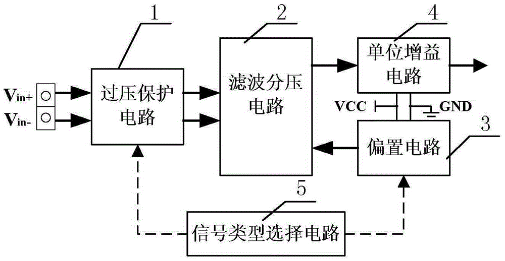
[0044] Specific implementation mode 1: refer to figure 1 To specifically describe this embodiment, a multi-type analog signal processing circuit powered by a single power supply described in this embodiment includes: an overvoltage protection circuit 1, a filter voltage divider circuit 2, a bias circuit 3, a unity gain circuit 4 and Signal type selection circuit 5;
[0045] The two signal input terminals of the overvoltage protection circuit 1 are respectively used as two signal input terminals of a multi-type analog signal processing circuit powered by a single power supply,
[0046] The two signal output ends of the overvoltage protection circuit 1 are respectively connected to the two signal input ends of the filter voltage divider circuit 2,
[0047] The reference signal input end of the filter voltage divider circuit 2 is connected to the reference signal output end of the bias circuit 3,
[0048] The filter signal output end of the filter voltage divider circuit 2 is c...
specific Embodiment approach 2
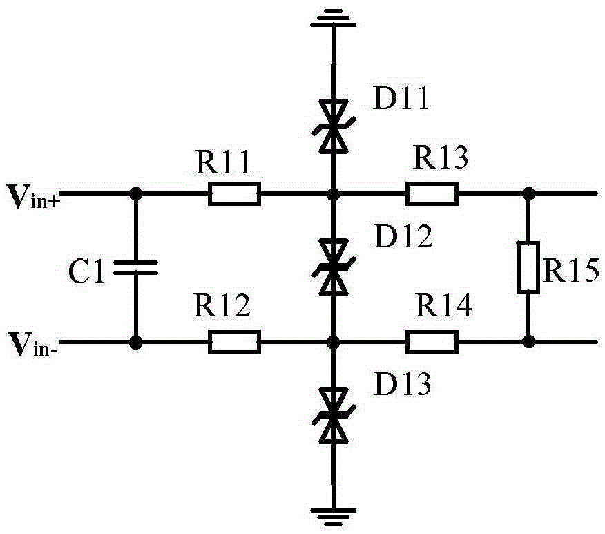
[0056] Specific implementation two: refer to image 3 This embodiment is described in detail. This embodiment further describes a multi-type analog signal processing circuit powered by a single power supply described in Embodiment 1. In this embodiment, the overvoltage protection circuit 1 includes: a capacitor C1 , No. 11 resistor R11, No.12 resistor R12, No.13 resistor R13, No.14 resistor R14, No.15 resistor R15, No.11 transient suppression diode D11, No.12 transient suppression diode D12 and a No. 3 TVS diode D13;
[0057] One end of the No. 1 capacitor C1 is connected to one end of the No. 1 resistor R11 and serves as a signal input terminal of the overvoltage protection circuit 1 at the same time, and the other end of the No. 1 capacitor C1 is connected to one end of the No. 1 resistor R12 and serves as an overvoltage The other signal input terminal of protection circuit 1,
[0058] The other end of resistor R11 No. 1 is connected to one end of TVS diode D11 No. 1, one ...
specific Embodiment approach 3
[0067] Specific implementation mode three: refer to Figure 4 This embodiment is described in detail. This embodiment further describes a multi-type analog signal processing circuit powered by a single power supply described in Embodiment 1. In this embodiment, the filter voltage divider circuit 2 includes: a No. 2 capacitor C2 , No. 3 capacitor C3, No. 21 resistor R21 and No. 22 resistor R22;
[0068] One end of the No. 21 resistor R21 is used as a signal input end of the filter voltage divider circuit 2,
[0069] The other end of the No. 21 resistor R21 is connected to one end of the No. 2 capacitor C2 and one end of the No. 3 capacitor C3 at the same time.
[0070] The other end of the No. 2 capacitor C2 is connected to one end of the No. 2 resistor R22, and serves as another signal input terminal and a reference signal input terminal of the filter voltage divider circuit 2 at the same time.
[0071] The other end of the No. 3 capacitor C3 is connected to the other end of...
PUM
 Abstract
Description
Claims
Application Information
 - R&D
- Intellectual Property
- Life Sciences
- Materials
- Tech Scout
- Unparalleled Data Quality
- Higher Quality Content
- 60% Fewer Hallucinations
Browse by: Latest US Patents, China's latest patents, Technical Efficacy Thesaurus, Application Domain, Technology Topic, Popular Technical Reports.
© 2025 PatSnap. All rights reserved.Legal|Privacy policy|Modern Slavery Act Transparency Statement|Sitemap|About US| Contact US: help@patsnap.com


