Supercharge Your Innovation With Domain-Expert AI Agents!

Blast furnace carbon block crane and carbon block installation method

A lifting truck and lifting device technology, which is used in cranes, transportation and packaging, load hoisting components, etc., can solve the problems of construction stagnation, affecting construction progress, hidden dangers of blast furnace safety, etc., so as to avoid secondary damage and prolong use. longevity and the effect of ensuring stable operation

Active Publication Date: 2016-07-27
CHINA FIRST METALLURGICAL GROUP
View PDF9 Cites 0 Cited by
  • Summary
  • Abstract
  • Description
  • Claims
  • Application Information

AI Technical Summary

Problems solved by technology

[0003] The coverage area of ​​the ring crane is limited and cannot completely cover the carbon block installation area; some carbon blocks are large in size and long in length. During the hoisting and position adjustment process, due to the lack of lifting points or uneven lifting force, it is easy to appear crooked. Cranes and other illegal operations affect the installation quality of carbon blocks, and there are certain potential safety hazards; and when the multi-rotating beams of the ring crane run at the same time, they will restrain each other, affecting the construction progress, and the construction will stagnate in serious cases; When hoisting the carbon block or adjusting the position of the carbon block, there may be an elevation problem, and the carbon block needs to be lifted repeatedly. Due to the large lifting distance, the electric hoist and the carbon block are connected by a wire rope, and the bottom of the carbon block is brushed with charcoal oil. It is prone to large sloshing, and it will collide with adjacent carbon blocks to cause damage to the carbon block. It is difficult to ensure the construction quality of the carbon block, which will bring safety hazards to the later operation of the blast furnace.

Method used


Image

  • Blast furnace carbon block crane and carbon block installation method
  • Blast furnace carbon block crane and carbon block installation method
  • Blast furnace carbon block crane and carbon block installation method

Examples


Embodiment Construction

[0033] In order to better understand the present invention, the present invention will be further described below in conjunction with the accompanying drawings and specific embodiments.

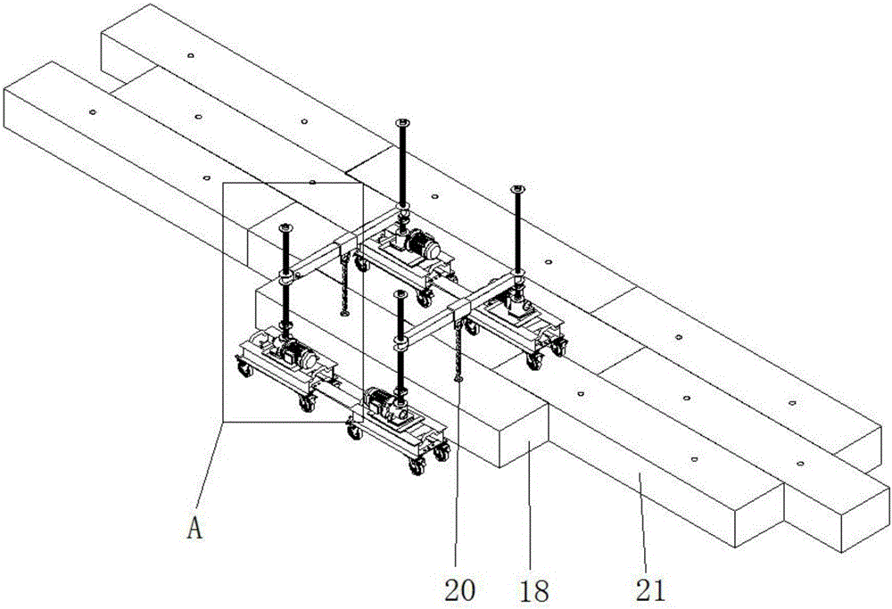
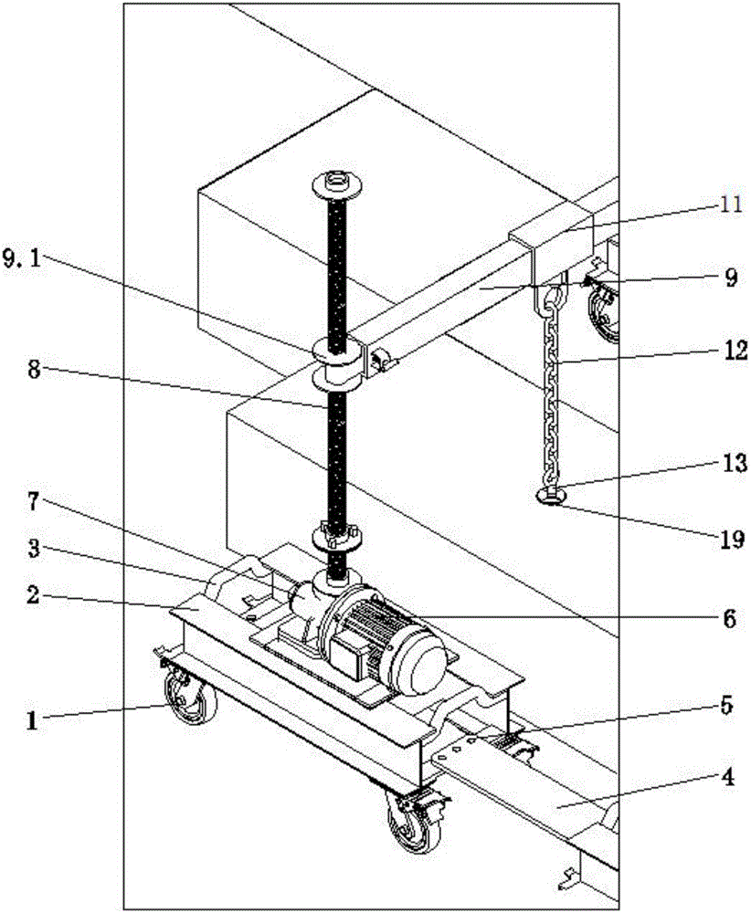
[0034] Such as figure 1 and figure 2 A blast furnace carbon block lifting vehicle shown includes two lifting devices located on both sides of the carbon block. The lifting device includes a base 2, a motor 6, a worm gear actuator 7 and a screw rod 8. The front end of the base 2 and Each rear end is equipped with a handle 3 (weldable, convenient for staff to move); the bottom of the four corners of the base 2 are respectively equipped with universal wheels 1 (weldable connection), and the upper part of the base 2 is fixedly installed with a motor 6 and a worm gear actuator 7 , the motor shaft of the motor 6 is connected to the input end of the worm gear actuator 7, and the output end of the worm gear actuator 7 is connected to the screw rod 8; a boom 9 is installed between the two lifting de...


PUM


Abstract

The invention discloses a blast furnace carbon block crane. The blast furnace carbon block crane comprises two lifting devices which are located on the two sides of a carbon block correspondingly. Each lifting device comprises a base, a motor, a worm and gear actuator and a screw rod, wherein the motor and the worm and gear actuator are fixedly installed on the upper portion of the base, a motor shaft of the motor is connected with the input end of the worm and gear actuator, and the output end of the worm and gear actuator is connected with the vertical screw rod. Lazy arms are installed between the two lifting devices. The two ends of each lazy arm are each provided with a screw opening. The two screw rods are matched with the two screw openings correspondingly. A steel chain is arranged on each lazy arm. The lower ends of the steel chains are connected with carbon brick lifting lugs. The carbon brick lifting lugs are matched with lifting holes of carbon blocks. The invention further discloses a blast furnace carbon block installation method. The blast furnace carbon block crane and the blast furnace carbon block installation method have the beneficial effects that the carbon blocks are lifted in a blast furnace, the lifting height is small, secondary damage caused by shaking in the lifting process of the carbon blocks is effectively avoided, and the safety of operators is greatly guaranteed.

Description

technical field [0001] The invention relates to the technical field of blast furnace construction, in particular to a blast furnace carbon block lifting vehicle and a carbon block installation method. Background technique [0002] During the hoisting construction of the carbon block at the bottom of the blast furnace, a ring crane is usually set up on the top of the blast furnace. The ring crane first lifts the carbon block into the blast furnace body through the steel wire rope, and then adjusts the position of the carbon block inside the furnace body. The adjustment of the carbon block position is very important. Carbon blocks have a significant impact on the construction quality. [0003] The coverage area of ​​the ring crane is limited and cannot completely cover the carbon block installation area; some carbon blocks are large in size and long in length. During the hoisting and position adjustment process, due to the lack of lifting points or uneven lifting force, it is ...

Claims


Application Information

Patent Timeline
Patent Type & Authority Applications(China)
IPC IPC(8): B66C25/00B66C1/12
CPCB66C1/12B66C25/00
Inventor 祝泽龙田红云夏春吴春桥
Owner CHINA FIRST METALLURGICAL GROUP
Features
  • R&D
  • Intellectual Property
  • Life Sciences
  • Materials
  • Tech Scout
  • Unparalleled Data Quality
  • Higher Quality Content
  • 60% Fewer Hallucinations
Learn More