Method for replacing crane main hook steel wire rope

A technology of steel wire rope and main hook, which is applied in the field of replacing the steel wire rope of the main hook of the crane. It can solve the problems of maintenance personnel such as high labor intensity, affecting normal use, and long time consumption, and achieves the effects of shortening maintenance time, reducing labor intensity, and improving operating efficiency.

Inactive Publication Date: 2016-07-27
SHANDONG IRON & STEEL CO LTD
View PDF4 Cites 20 Cited by
  • Summary
  • Abstract
  • Description
  • Claims
  • Application Information

AI Technical Summary

Problems solved by technology

[0004] At present, the general method used to replace the steel wire rope 2 is to remove the old steel wire rope from the drum 1 and the pulley block, and use the hemp rope as a guide rope to thread the new steel wire rope that has been cut in advance according to the driving and lifting distance in turn around the precessive pulley and the fixed pulley. , and then fix the two ends of the new steel wire rope on the two ends of the reel 1; because the position of the fixed pulley and the reel 1 is relatively high, thread the new steel wire rope into the fixed pulley block 3 and fix it on the reel 1 It is necessary to manually pull up the new steel wire rope, and the labor intensity of the maintenance personnel is high, time-consuming, and low in efficiency; After manually fixing the two ends of the new wire rope on the two ends of the reel 1, the torsional force generated by the new wire rope is not easy to release, and the main hook 5 will be driven to twist through the movable pulley block 3, and even when the torsional force is large Drive the main hook 5 to rotate, and make the new steel wire ropes wound on different movable pulleys kink together, affecting normal use

Method used


Image

  • Method for replacing crane main hook steel wire rope
  • Method for replacing crane main hook steel wire rope
  • Method for replacing crane main hook steel wire rope

Examples


Embodiment Construction

[0034] In order to enable those skilled in the art to better understand the technical solutions in the present invention, the technical solutions in the embodiments of the present invention will be clearly and completely described below in conjunction with the drawings in the embodiments of the present invention. Obviously, the described The embodiments are only some of the embodiments of the present invention, not all of them. Based on the embodiments of the present invention, all other embodiments obtained by persons of ordinary skill in the art without making creative efforts shall fall within the protection scope of the present invention.

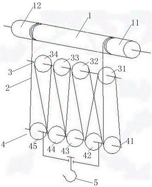
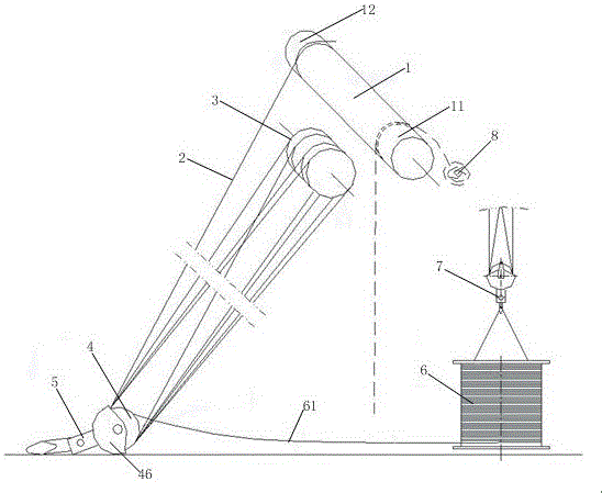
[0035] based on figure 1 For the winding method of the main hook wire rope shown, please refer to figure 2, which is a schematic diagram of replacing the wire rope of the main hook of the vehicle provided by the embodiment of the present invention, and the method for replacing the wire rope of the main hook of the vehicle is according...


PUM


Abstract

The invention provides a method for replacing a crane main hook steel wire rope. Firstly, an old steel wire rope at one end of a drum is dismounted; the rope head of the dismounted old steel wire rope is connected with one end of a new steel wire rope; the other end of the old steel wire rope is still fixed on the drum; a main lifting hook is ascended; and under winding drive of the drum, and self power of equipment is used for enabling the old steel wire rope to tow the new steel wire rope to wind in a pulley set so as to finish replacement of the steel wire rope. The method for replacing the crane main hook steel wire rope, provided by the invention, fully uses self power of the equipment in the replacing process, effectively improves the operation efficiency, shortens the maintenance time, needs no manual drawing, and largely reduces the labor intensity.

Description

technical field [0001] The invention relates to the technical field of crane equipment, in particular to a method for replacing a steel wire rope of a main hook of a crane. Background technique [0002] A crane refers to a multi-action hoisting machine that lifts vertically and carries heavy objects horizontally within a certain range, and belongs to material handling machinery. According to the structural form, cranes are mainly divided into light and small lifting equipment, bridge type (bridge type, gantry type) cranes, jib type (self-propelled, tower type, portal type, railway type, pontoon type, mast type) cranes, Cable crane. What we usually call driving is a kind of bridge crane. Driving is generally composed of three parts: mechanical, electrical and metal structures. The mechanical part is divided into three mechanisms, namely the lifting mechanism, the trolley running mechanism and the cart running mechanism. The hoisting mechanism is used to vertically lift it...

Claims


Application Information

Patent Timeline
Patent Type & Authority Applications(China)
IPC IPC(8): B66D1/28B66D1/36
Inventor 孙吉才李瑞峰郑宏祥林士杰
Owner SHANDONG IRON & STEEL CO LTD
Why Eureka
Try Eureka