
A double-cover double-compression pressure vessel

A pressure vessel and pressing technology, applied in the field of pressure equipment, can solve the problems of weak tightness, troublesome opening and closing, poor sealing effect, etc., so as to increase the sealing performance, increase the impact resistance, press location-accurate effect

Active Publication Date: 2018-05-01
江苏申强特种设备有限公司
View PDF5 Cites 0 Cited by
  • Summary
  • Abstract
  • Description
  • Claims
  • Application Information

AI Technical Summary

Problems solved by technology

[0002] The pressure vessel is usually used to contain gas or liquid, and must be able to withstand relatively high pressure. The pressure vessel is usually composed of a tank body and a tank cover. The liquid (gas) is discharged, and the hydraulic port is closed by the hydraulic cover. When using the hydraulic port, the hydraulic cover needs to be opened as a whole; and when necessary, the tank body needs to be opened as a whole, and a flange is usually used between the tank cover and the tank body. The fixed connection of the plate is usually installed by bolts or hinges. When the tank cover needs to be opened, the bolts and hinges need to be removed. It is very troublesome to open and cover; and the usual flange seal installation only takes two The flange plate is fixed and installed by bolts, and its sealing effect is not good. Not only is it inconvenient to install, disassemble and open, but also the fastening is not strong; therefore, it is not very convenient to open the hydraulic cover and tank body of traditional pressure vessels.

Method used


Image

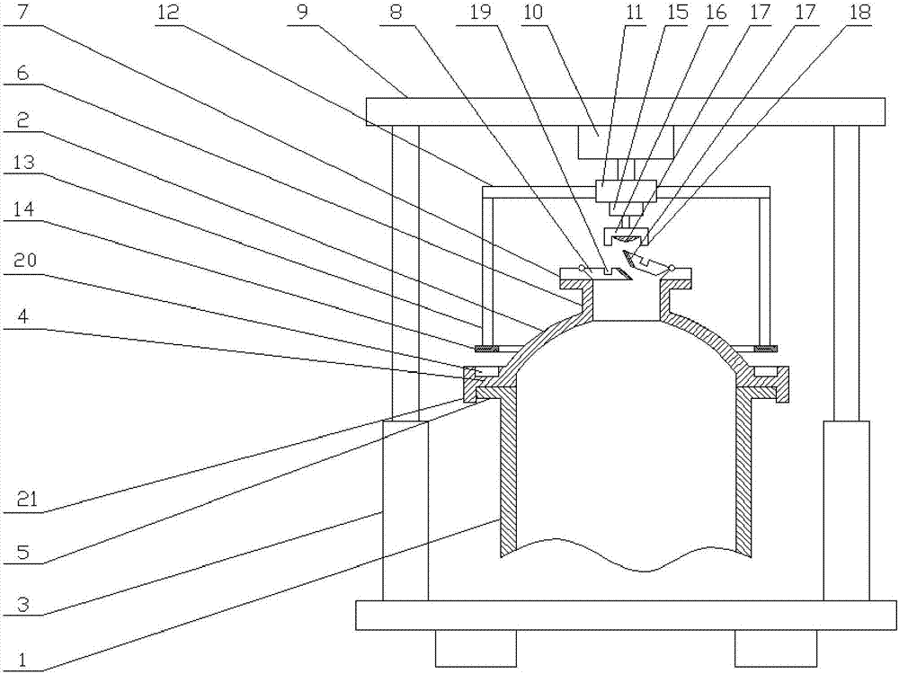
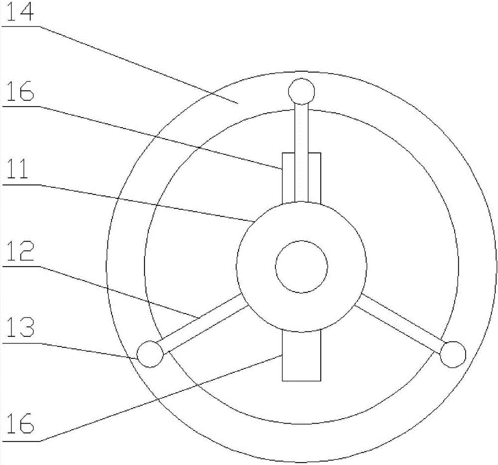
  • A double-cover double-compression pressure vessel
  • A double-cover double-compression pressure vessel

Examples


Embodiment Construction

[0019] The present invention will be further illustrated below in conjunction with the accompanying drawings and specific embodiments. This embodiment is implemented on the premise of the technical solution of the present invention. It should be understood that these embodiments are only used to illustrate the present invention and are not intended to limit the scope of the present invention.

[0020] Such as figure 1 and figure 2 As shown, a double-cover double-compression pressure vessel includes a tank body 1, a tank cover 2 installed on the tank body 1, a height-adjustable mobile bracket 3, and a compression device installed on the mobile bracket 3; The connection between the tank cover 2 and the tank body 1 is respectively provided with an upper ring mounting plate 4 and a lower ring mounting plate 5; and the tank cover 2 is provided with a hydraulic port 6, and the hydraulic port 6 is provided with A detachable hydraulic cover 7 is installed; the plugging cover in the ...


PUM


Abstract

The invention discloses a dual compression pressure vessel with two cover bodies. The dual compression pressure vessel comprises a tank body, a tank cover mounted on the tank body, a height-adjustable movable support, and a compression device mounted on the movable support, wherein an upper circular ring mounting plate and a lower circular ring mounting plate are arranged at the joint between the tank cover and the tank body; a hydraulic opening is formed in the tank cover; and a detachable hydraulic cover is mounted above the hydraulic opening. The dual compression pressure vessel provided by the invention has the advantages that two door covers are closed in a compression type; the door slots of the two door covers can be totally pressed and blocked by a strip pressing plate which is mounted through a second hydraulic cylinder, so that the door covers are very convenient to open and close; a sealing rubber mat is arranged on the strip pressing plate, so that the sealing performance can be improved after the door slots are pressed and pressure leakage can be avoided; and clamping blocks arranged on the stripe pressing plate can press into clamping grooves formed in the door covers, so that not only can the positioning function be achieved, but also the stability and the anti-impact capability can be improved, and the door covers can be prevented from being opened due to excessive pressure or unexpected reasons.

Description

technical field [0001] The invention relates to a pressure device, in particular to a double-cover double-compression pressure vessel. Background technique [0002] The pressure vessel is usually used to contain gas or liquid, and must be able to withstand relatively high pressure. The pressure vessel is usually composed of a tank body and a tank cover. The liquid (gas) is discharged, and the hydraulic port is closed by the hydraulic cover. When using the hydraulic port, the hydraulic cover needs to be opened as a whole; and when necessary, the tank body needs to be opened as a whole, and a flange is usually used between the tank cover and the tank body. The fixed connection of the plate is usually installed by bolts or hinges. When the tank cover needs to be opened, the bolts and hinges need to be removed. It is very troublesome to open and cover; and the usual flange seal installation only takes two The flange plate is fixed and installed by bolts, and its sealing effect ...

Claims


Application Information

Patent Timeline
Patent Type & Authority Patents(China)
IPC IPC(8): F16J13/16F16J13/00
CPCF16J13/00F16J13/16
Inventor 单曙光阎冰宋佐涛金全国
Owner 江苏申强特种设备有限公司
Learn More