Pressure reduction type backflow preventing device

A backflow preventer and pressure reducing valve technology, applied in the direction of control valve, functional valve type, engine components, etc., to achieve the effects of stable performance, long service life and simple structure

Inactive Publication Date: 2016-07-27
HARBIN REYAX TECH CO LTD
View PDF0 Cites 0 Cited by
  • Summary
  • Abstract
  • Description
  • Claims
  • Application Information

AI Technical Summary

Problems solved by technology

The currently used backflow preventer uses a diaphragm to transmit pressure and seal the decompression part. However, due to the complicated processing technology of the diaphragm, the product quality is unstable, which affects the life of the backflow preventer.
In addition, due to the reaction force of the diaphragm, it will have a certain impact on the accuracy of the design of the spring force at the decompression part, and affect the first-time assembly pass rate of the product.

Method used


Image

  • Pressure reduction type backflow preventing device

Examples


Embodiment 1

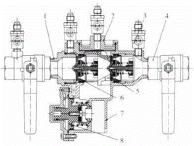
[0014] A decompression backflow preventer. The decompression backflow preventer is composed of two check valves that work independently. A differential pressure relief valve is connected externally between the two valves. Directly connect two ball valves for maintenance and four elastic sealing test ball valves to form a complete decompression backflow preventer. In the case of water supply, the water in the main water pipeline is decompressed from the check valve at the inlet position. The outlet of the check valve at the position from the area to the outlet supplies water to the user, and the high-pressure water imported by the check valve at the inlet position is directly connected to the upper chamber of the diaphragm of the pressure reducing valve, while the lower chamber of the diaphragm communicates with the inlet of the check valve at the outlet position. A certain pressure difference pushes the diaphragm to the right, the pressure reducing valve closes, and the water...


PUM


Abstract

The invention provides a pressure reduction type backflow preventing device. According to an existing backflow preventing device, a pressure reduction portion adopts a membrane for transferring pressure and is sealed, however, due to the fact that a processing technique of the membrane is complex, the product quality is unstable, and the service life is influenced. The pressure reduction type backflow preventing device is composed of two check valves which work independently. A differential pressure relief valve is externally connected between the two check valves. The two ends of each check valve are further directly connected with two ball valves used for maintenance and four elastic sealed test ball valves, and therefore the complete pressure reduction type backflow preventing device is formed. Under the water supply condition, water in a main water delivery pipeline passes through a pressure reduction area from the check valve in the inlet position, reaches the outlet of the check valve in the outlet position, and is supplied to users. High-pressure water at the inlet of the check valve in the inlet position is directly led into an upper membrane cavity of a pressure reduction valve, and a lower membrane cavity communicates with the inlet of the check valve in the outlet position. Due to the fact that a certain pressure difference exists, a membrane is pushed to move rightwards, the pressure reduction valve is closed, and water supply is normal.

Description

Technical field: [0001] The invention relates to a decompression type backflow preventer. Background technique: [0002] The decompression backflow preventer (hereinafter referred to as the backflow preventer), as a valve component that can effectively prevent the dirty water in the branch circuit from flowing back to the main road, is widely used in developed countries such as Europe and the United States. In China, common check valves are mainly used to prevent water backflow, and there are not many applications of backflow preventers. The currently used backflow preventer uses a diaphragm to transmit pressure and seal the decompression part, but due to the complicated processing technology of the diaphragm, the product quality is unstable, which affects the life of the backflow preventer. In addition, due to the reaction force of the diaphragm, it will have a certain impact on the accuracy of the design of the spring force at the decompression part, and affect the firs...

Claims


Application Information

Patent Timeline
Patent Type & Authority Applications(China)
IPC IPC(8): F16K15/00F16K13/00
Inventor 张淼
Owner HARBIN REYAX TECH CO LTD
Why Eureka
Try Eureka