
Water circulation type damping leg for mechanical equipment

A technology of mechanical equipment and water circulation, which is applied in the direction of mechanical equipment, springs/shock absorbers, shock absorbers, etc., can solve the problems of heavy weight, exhaustion of shock absorbers, economic losses of production enterprises, etc., and achieve simple structure and high performance. Stable, long-lasting effect

Inactive Publication Date: 2016-07-27
ZHEJIANG IND POLYTECHNIC COLLEGE
View PDF2 Cites 0 Cited by
  • Summary
  • Abstract
  • Description
  • Claims
  • Application Information

AI Technical Summary

Problems solved by technology

Due to the large size and weight of large-scale mechanical equipment, factories or enterprises need to consider the placement of large-scale mechanical equipment after purchasing large-scale mechanical equipment. In most cases, large-scale mechanical equipment is placed directly on the ground, and its bottom is generally directly connected to the ground. Contact, or simply add a gasket under the tripod, the purpose is to prevent the machine tool from crushing and fracturing the ground. The existing mechanical equipment shock absorption or protection measures for contact with the ground are too simple and the effect is not good. For the work For a machine that vibrates strongly at times, a simple shock absorber will not have any substantial effect. After a long period of operation, the shock absorber will wear out, and because the shock absorber is not in place, the machine tool will be accelerated. The damage of itself and internal parts has caused economic losses to the production enterprise

Method used


Image

  • Water circulation type damping leg for mechanical equipment

Examples


Embodiment Construction

[0011] The present invention will be further described below in conjunction with accompanying drawing:

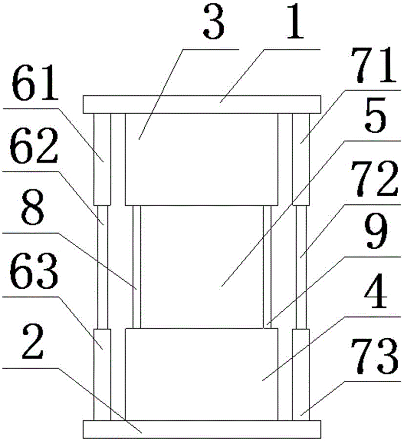
[0012] Such as figure 1 Shown: the present invention comprises base 2, support platform 1, left balance column, right balance column, first water tank 3 and second water tank 4, and the two ends of base 2 and support platform 1 are carried out by left balance column and right balance column respectively Support, the first water tank 3 is arranged on the bottom of the support platform 1, the second water tank 4 is arranged on the upper side of the base 2, a circulating water pump 5 is arranged between the first water tank 3 and the second water tank 3, and the two sides of the circulating water pump 5 are respectively A first sealing ring 8 and a second sealing ring 9 are provided.

[0013] Such as figure 1 As shown, the left balance column includes a first threaded barrel 61 and a second threaded barrel 63 connecting the base 2 and the support platform 1 , and a first scr...


PUM


Abstract

The invention discloses a water circulation type damping leg for mechanical equipment. The damping leg comprises a base, a supporting platform, a left balance column, a right balance column, a first water tank and a second water tank, wherein two ends of the base and two ends of the supporting platform are supported by the aid of the left balance column and the right balance column respectively, the first water tank is arranged at the bottom of the supporting platform, the second water tank is arranged on the upper side of the base, a circulating water pump is arranged between the first water tank and the second water tank, and a first sealing ring and a second sealing ring are arranged on two sides of the circulating water pump respectively. According to the damping leg, the first water tank is arranged at the bottom of the supporting platform, the second water tank is arranged on the upper side of the base, the circulating water pump is arranged between the first water tank and the second water tank, and the vibratory sensation of the mechanical equipment is relieved through hydraulic pressure; the damping leg has the advantages of simple structure, stable performance and longer service life.

Description

technical field [0001] The invention relates to a shock absorbing device, in particular to a shock absorbing leg of a water circulation type mechanical equipment. Background technique [0002] With the rapid development of China's manufacturing industry, the machinery and equipment required by the manufacturing industry are also developing towards large-scale and heavy weight. Due to the large size and weight of large-scale mechanical equipment, factories or enterprises need to consider the placement of large-scale mechanical equipment after purchasing large-scale mechanical equipment. In most cases, large-scale mechanical equipment is placed directly on the ground, and its bottom is generally directly connected to the ground. Contact, or simply add a gasket under the tripod, the purpose is to prevent the machine tool from crushing and fracturing the ground. The existing mechanical equipment shock absorption or protection measures for contact with the ground are too simple a...

Claims


Application Information

Patent Timeline
Patent Type & Authority Applications(China)
IPC IPC(8): F16M7/00F16F15/023F16F9/10
CPCF16M7/00F16F9/10F16F15/023F16F2222/12
Inventor 王林超
Owner ZHEJIANG IND POLYTECHNIC COLLEGE
Learn More