Heater

A heater and heating zone technology, applied in water heaters, fluid heaters, indirect heat exchangers, etc., can solve problems such as inability to directly use heater hot liquid, inability to achieve heat exchange, inability to solve poor thermal efficiency, etc.

Inactive Publication Date: 2016-07-27
林圳田
View PDF16 Cites 0 Cited by
  • Summary
  • Abstract
  • Description
  • Claims
  • Application Information

AI Technical Summary

Problems solved by technology

Although China Taiwan Patent No. M338338 discloses that the top surface of the transverse partition is laid with a heat insulating material, yet in order to avoid heat exchange between the gas on the top surface of the transverse partition and each compartment, this structure cannot achieve real-time The heat exchange between the hottest hot liquid and the cooler liquid around the heater is blocked nearby, and the heated hot liquid needs to pass through the diversion extending from the top of the bulkhead to the bottom of the hot and cold compartment bucket In addition to the extremely long flow path and the easy loss of heat energy, the higher temperature liquid will further mix with the lower temperature liquid at a lower place and then flow to a higher place to the liquid outlet, which cannot solve the thermal efficiency caused by the mixing of hot and cold liquids. Poor and does not take direct advantage of the hottest hydrothermal fluid around the heater

Method used


Image

  • Heater
  • Heater
  • Heater

Examples


Embodiment Construction

[0030] The following examples illustrate possible implementations of the present invention, but are not intended to limit the protection scope of the present invention.

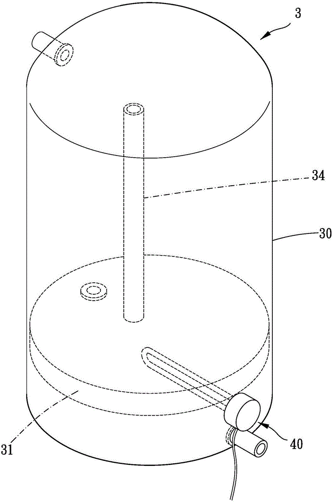
[0031] See Figure 3 to Figure 5 , which shows a preferred embodiment of the present invention, the heater 3 of the present invention includes a cylinder 30 and a heating device 40 .

[0032] The inside of the cylinder 30 is provided with a heat insulating portion 31, a heating area 32 and a non-heating area 33 located on opposite sides of the heat insulating portion 31, a heat insulating portion 31 and connected to the heating area 32 And the heat flow conduit 34 of the non-heating zone 33, and a cold flow channel 35 communicating with the heating zone 32 and the non-heating zone 33, the cylinder 30 is also provided with a water inlet 36 and the inside of the cylinder 30 A water outlet 37 , the heat flow conduit 34 extends from the heating zone 32 toward the water outlet 37 . The heating device 40 (such as...


PUM


Abstract

The invention relates to a heater, comprising a barrel, and a heating device. The internal of the barrel is provided with a heat insulation portion, and a heating region and a non-heating region on two opposite sides of the heat insulation portion, a hot flow conduit passing through the heat insulation portion and communicating the heating region and the non-heating region, and a cold flow channel communicating the heating region with the non-heating region. The barrel is additionally provided with a water inlet and a water outlet communicating with the internal of the barrel. The hot flow conduit extends to a direction close to the water outlet from the heating region. The heating device is arranged in the barrel and extends into the heating region. The heater is advantaged by improving heating effect, ensuring heat energy not to dissipate, and saving energy, and high outlet water temperature and no wait for hot water.

Description

technical field [0001] The present invention relates to heaters. Background technique [0002] Such as figure 1 As shown, the conventional heater mainly includes a cylinder body 10, a heating pipe 11, a water inlet pipe 12 and a water outlet pipe 13. There is a partition 14 inside the cylinder body 10, and an inner top plate 15 above the partition 14, and the water inlet pipe 12 passes upwards. The inner top plate 15 comes out, and the water inlet pipe 12 guides water into the outer periphery of the partition 14 , and the inner top plate 15 has a flow port 16 . [0003] In addition, if figure 2 As shown, another conventional heater mainly includes a cylinder body 20, a heating pipe 21, a water inlet pipe 22, and a water outlet pipe 23. There is a partition 24 inside the cylinder body 20, and there is a heating zone 240 inside, and the heating zone 240 has a heating tube. 21 is introduced, and there is an outlet pipe 23 above the heating zone 240 to lead out of the cylind...

Claims


Application Information

Patent Timeline
Patent Type & Authority Applications(China)
IPC IPC(8): F24H1/20F24H9/18F24H9/00
CPCF24H1/0018F24H1/202F24H9/0005F24H9/1818F24H2250/02F24H9/0015F24H9/0021F28D20/0039F28D2020/0086F28D2020/0069Y02E60/14F24H9/133
Inventor 林圳田
Owner 林圳田
Why Eureka
Try Eureka