
Temperature control device for keeping temperature of industrial furnace

A technology for temperature control devices and industrial furnaces, which is applied to furnaces, furnace components, and electric charge control, etc. It can solve problems such as high furnace body, failure to reach ideal temperature, and inability to save energy.

Inactive Publication Date: 2022-03-04
盐城市苏瑞思电子有限责任公司
View PDF6 Cites 0 Cited by
  • Summary
  • Abstract
  • Description
  • Claims
  • Application Information

AI Technical Summary

Problems solved by technology

[0003] After the existing industrial furnace is burned, the problem of the furnace body is very high. At this time, the furnace door must be opened to take out the heated materials in the furnace for processing, so the furnace door can only be opened manually. Because the temperature of the furnace door is high, it is prone to danger
[0004] Moreover, there are industrial furnaces that need to frequently open and close the furnace door to perform operations such as feeding into the industrial furnace. When the furnace door is opened and closed, a large amount of heat in the industrial furnace will be lost, which will easily cause the temperature in the industrial furnace to drop sharply. When the parts are subsequently processed, the ideal temperature cannot be reached, and a relatively stable processing environment cannot be provided for the parts. Moreover, when the temperature in the industrial furnace is lost in a large amount, supplementary heating is required. At this time, the fuel resources required for heating will increase sharply. Large, unable to achieve the purpose of saving energy

Method used


Image

  • Temperature control device for keeping temperature of industrial furnace
  • Temperature control device for keeping temperature of industrial furnace
  • Temperature control device for keeping temperature of industrial furnace

Examples


Embodiment

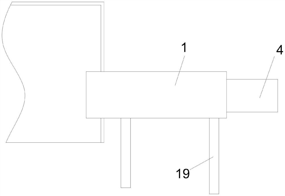
[0033] Please refer to Figure 1-Figure 3 as shown, figure 1 It is a combined structure schematic diagram of the present invention and industrial furnace;

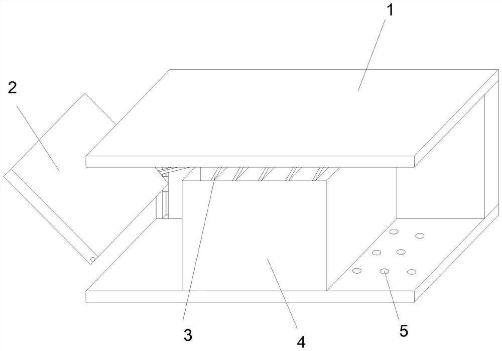
[0034] figure 2 It is a schematic diagram of a partially cut-away three-dimensional structure of the present invention;

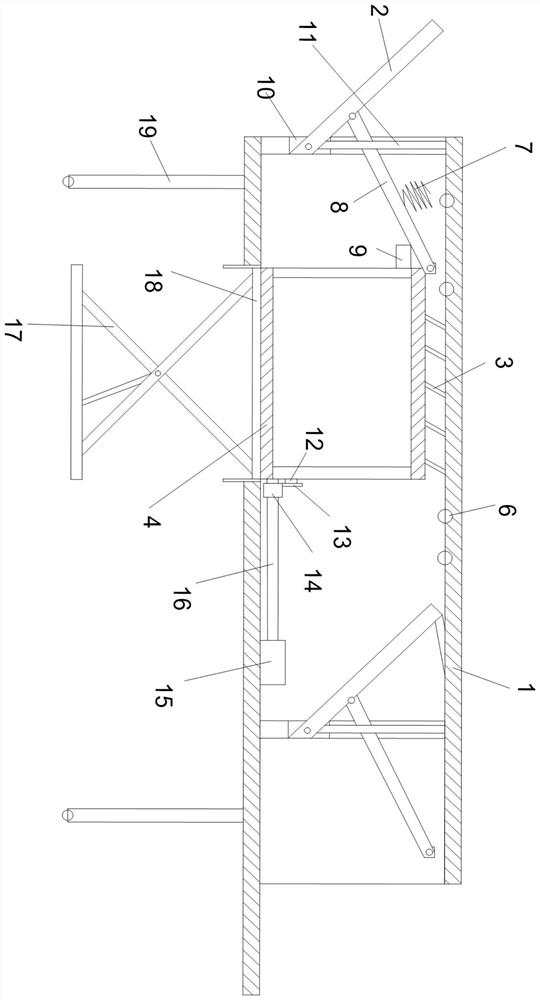
[0035] image 3 It is a cross-sectional combined schematic diagram of the present invention.

[0036]The embodiment of the present application provides a temperature control device for maintaining the temperature of an industrial furnace, including a box body 1 adapted to the furnace mouth of the industrial furnace, and a material box 4 is slid inside the box body 1, and both ends of the material box 4 can be disassembled A material door is provided, and both ends of the box body 1 are provided with a box door assembly for blocking the box body 1, and a drive assembly for driving the material box 4 to move is arranged inside the box body 1. The temperature control device for maintaining the temper...


PUM


Abstract

The invention provides a temperature control device for keeping the temperature of an industrial furnace, and relates to the technical field of industrial furnace heat preservation. Comprising a box body matched with a furnace opening of the industrial furnace, a material box is arranged in the box body in a sliding mode, material doors are detachably arranged at the two ends of the material box, box door assemblies for blocking the box body are arranged at the two ends of the box body, and a driving assembly for driving the material box to move is arranged in the box body. According to the technical scheme, the box body matched with the furnace opening of the industrial furnace can provide an access channel for parts entering and exiting the industrial furnace, the box door assemblies for blocking the box body are arranged at the two ends of the box body and can shield the furnace door opening of the industrial furnace, heat in the industrial furnace is prevented from being greatly dissipated when the parts are added, and the service life of the industrial furnace is prolonged. And the part machining environment is affected.

Description

technical field [0001] The invention relates to the technical field of industrial furnace heat preservation, in particular to a temperature control device for maintaining the temperature of an industrial furnace. Background technique [0002] The industrial furnace using natural gas, coal gas or fuel oil as fuel, its working principle is to place the workpiece to be heated in the furnace, heat up to the temperature required by the process, keep warm or evenly temperature. Industrial furnaces are widely used in casting, forging, metal heat treatment, metallurgy, petroleum, glass and other fields. [0003] After the existing industrial furnace is burned, the problem of the furnace body is very high. At this time, the furnace door must be opened to take out the heated materials in the furnace for processing, so the furnace door can only be opened manually. Because the temperature of the furnace door is high, it is prone to danger. [0004] Moreover, there are industrial furna...

Claims


Application Information

Patent Timeline
Patent Type & Authority Applications(China)
IPC IPC(8): F27D3/00F27D1/18
CPCF27D3/00F27D1/1858F27D2003/0051
Inventor 陈孙杰
Owner 盐城市苏瑞思电子有限责任公司
Learn More