
Counter force applying device, mask fabrication device and corresponding method

A technology of applying device and resisting force, applied in the direction of manufacturing tools, auxiliary devices, workpiece clamping devices, etc., can solve problems such as uneven force application, affecting the stability of the frame 104, deformation of the frame 104, etc., to ensure contact integrity, Overcoming the effect of poor contact

Active Publication Date: 2016-07-27
BOE TECH GRP CO LTD +1
View PDF12 Cites 6 Cited by
  • Summary
  • Abstract
  • Description
  • Claims
  • Application Information

AI Technical Summary

Problems solved by technology

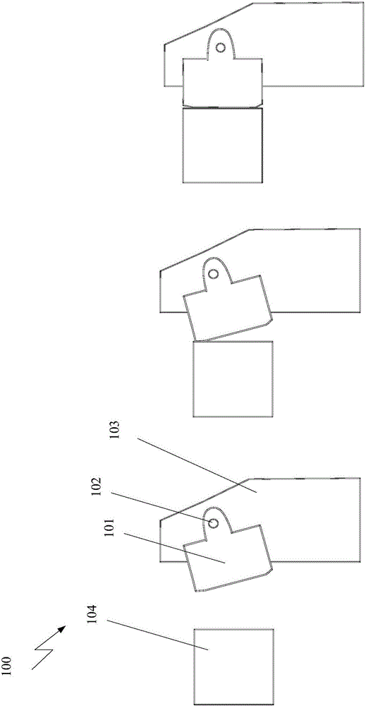
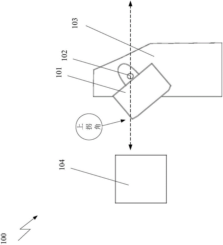
[0005] However, since the contact member 101 has a large degree of freedom of movement, sometimes when the contact member 101 is in contact with the frame 104, the frame 104 only touches a corner of the contact member 101, causing the contact member 101 to be unable to fully contact the frame. A state of uneven force is generated, which in turn affects the stability of the frame 104 product and deforms the frame 104 product

Method used


Image

  • Counter force applying device, mask fabrication device and corresponding method
  • Counter force applying device, mask fabrication device and corresponding method
  • Counter force applying device, mask fabrication device and corresponding method

Examples


Embodiment Construction

[0023] In order for those skilled in the art to better understand the solution of the present invention, the resistive force applying device, mask manufacturing device and corresponding method provided by the embodiments of the present invention are further described in detail below with reference to the accompanying drawings and specific embodiments. Obviously, the described embodiments are some, but not all, embodiments of the present invention. Based on the described embodiments of the present invention, all other embodiments obtained by those of ordinary skill in the art without creative work fall within the protection scope of the present invention.

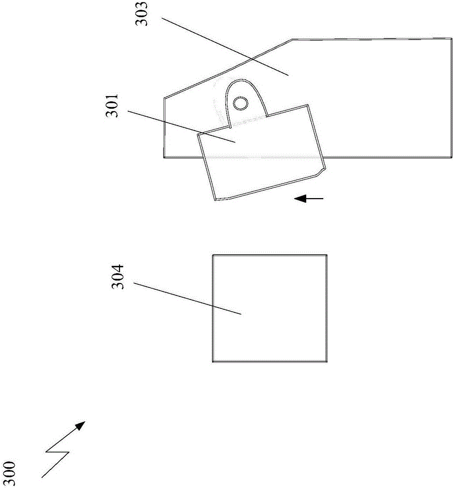
[0024] Now refer to image 3 , which shows an opposing force applying device 300 according to an embodiment of the present invention. like image 3 As shown in , the resistive force application device 300 includes: an application device body 303; a contact member 301 pivotally connected to the application device body 303, ...


PUM


Abstract

The invention discloses a counter force applying device, a mask fabrication device and a corresponding method. The counter force applying device comprises one or more applying device main bodies and one or more contact members, wherein the contact members are pivoted with each applying device main body and is configured to be in contact with a frame, the applying device main bodies are configured to drive the contact members by moving and applying a counter force to the frame by the contact members, and the rotation freedom of the contact members is limited.

Description

technical field [0001] Embodiments of the present invention relate to the field of display panel manufacturing, and more particularly, to a resistive force applying device, a mask manufacturing device and a corresponding method. Background technique [0002] The fine metal mask (Fine Metal Mask, FMM) mode of organic light emitting diode (Organic Light-Emitting Diode, OLED) panel processing is to vaporize the OLED material on the low temperature polysilicon (LowTemperaturePoly-Silicon, LTPS) backplane according to a predetermined procedure by vapor deposition , in which the red, green and blue organic matter is evaporated to the specified position using the pattern on the FMM. For this, the FMM needs to be made first. [0003] When making FMM, a frame (Frame) needs to be prepared first, and then a counterforce (CounterForce, CF) applying device is applied to the frame to pre-deform the frame, and finally the FMM sheet is welded on the frame. Through the pre-deformation of t...

Claims


Application Information

Patent Timeline
Patent Type & Authority Applications(China)
IPC IPC(8): H01L51/56H01L51/00C23C14/04H10K99/00
CPCC23C14/042H10K71/164H10K71/166B25B1/24B25B11/02B23K37/0443H10K71/00
Inventor 林治明王震黄俊杰张健
Owner BOE TECH GRP CO LTD
Learn More