
hydraulic excavator

A technology for hydraulic excavators and engines, which is applied in the field of hydraulic excavators, and can solve the problems of communication terminals with low heat resistance and low temperature, and difficult electrical assembly units to be arranged on the operator's seat, etc.

Active Publication Date: 2021-09-07
KOMATSU LTD
View PDF7 Cites 0 Cited by
  • Summary
  • Abstract
  • Description
  • Claims
  • Application Information

AI Technical Summary

Problems solved by technology

[0004] However, as an electrical component, in addition to the above-mentioned processing device, a communication terminal with a lower heat-resistant temperature may be added.
Although these electrical components are unitized into electrical component units, the increase in the size of the electrical component units due to the increase in electrical components cannot be avoided. Therefore, it is difficult to arrange the electrical component units in terms of space constraints. side of operator seat

Method used


Image

  • hydraulic excavator
  • hydraulic excavator
  • hydraulic excavator

Examples


Embodiment Construction

[0024] [Outline structure of hydraulic excavator]

[0025] One embodiment of the present invention will be described based on the drawings.

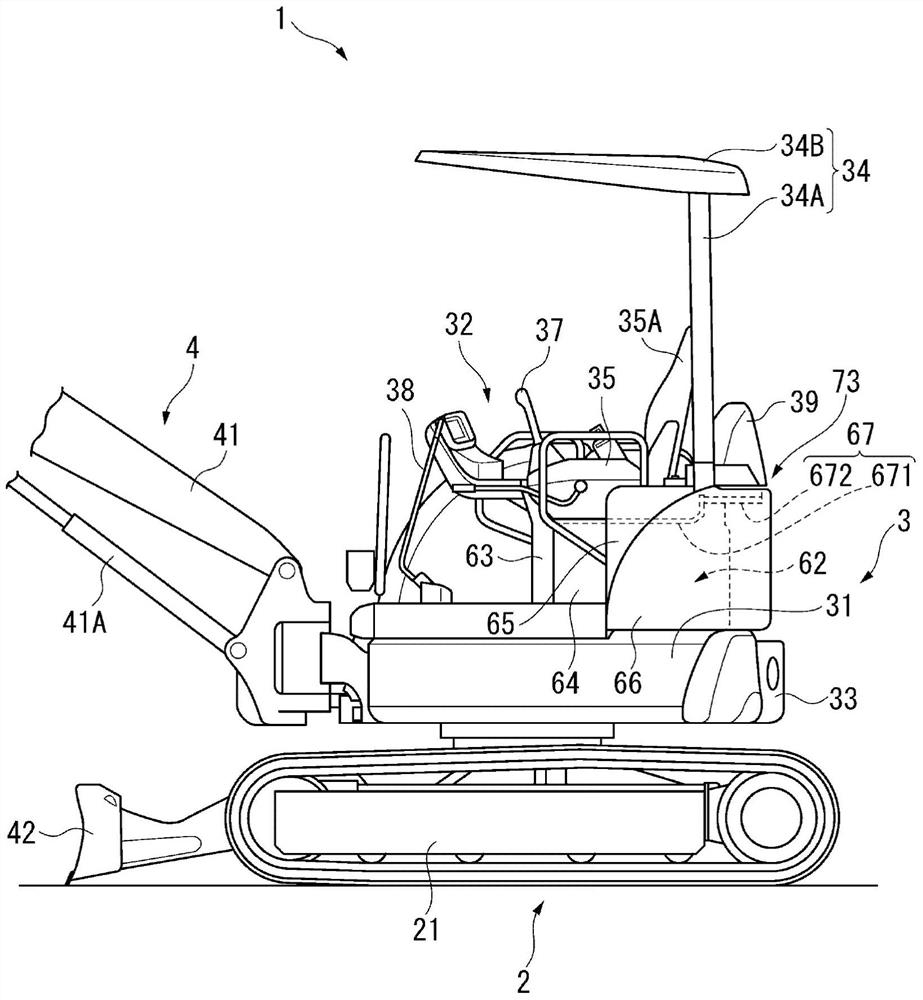
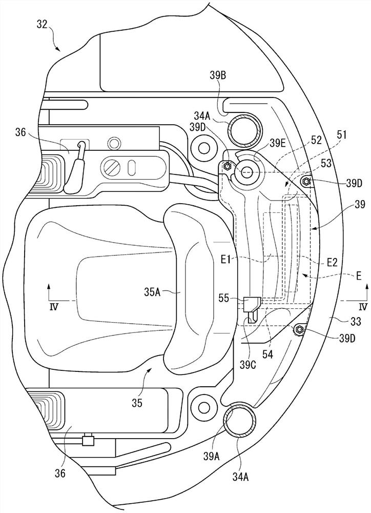
[0026] figure 1 It is a side view showing the hydraulic excavator 1 according to this embodiment. figure 2 It is a plan view showing the cab of the hydraulic excavator.

[0027] exist figure 1 , figure 2 Among them, the hydraulic excavator 1 includes: a crawler-type undercarriage 2 driven by a hydraulic motor; an upper revolving body 3 rotatably provided on the upper part of the undercarriage 2; The hydraulic excavator 1 is configured as a small-sized hydraulic excavator as a work implement 4 for excavating soil or the like.

[0028] Of these, the upper revolving body 3 is provided with a revolving frame 31 in which a not-shown revolving hydraulic motor is provided substantially at the center. On the revolving frame 31 , the work implement 4 , the cab 32 into which the operator rides, and the counterweight 33 are arranged in this...


PUM


Abstract

A hydraulic excavator provided with an upper revolving body, the hydraulic excavator comprising: an engine room (62) configured for an engine (61); a covering member (67) covering the engine room (62) in an airtight manner; The top; the electrical equipment unit (E), which has electrical equipment (E1, E2); and the support member (672), which supports the electrical equipment unit (E) from below through the spacer (71), and the electrical equipment The unit (E) is disposed above the covering member (67) via the spacer (71).

Description

technical field [0001] The invention relates to a hydraulic excavator. Background technique [0002] Conventionally, electrical components such as a processing device (body controller) for processing information from sensors mounted at predetermined locations have been mounted on hydraulic excavators. Electrical components have a lower heat-resistant temperature than other components and need to be less susceptible to heat from the engine room, so cooling with a dedicated cooling structure has been proposed (for example, refer to Patent Document 1). [0003] In Patent Document 1, in a roof-type small hydraulic excavator, electrical components are arranged on the side of an operator's seat, and the electrical components are covered by an electrical component cover. The electrical component cover is provided with an air passage having an air suction hole at one end for sucking in external air. The other end of the air passage is opened at a position immediately before taking...

Claims


Application Information

Patent Timeline
Patent Type & Authority Patents(China)
IPC IPC(8): E02F9/00
CPCE02F3/325E02F9/0858
Inventor 渡边馨
Owner KOMATSU LTD
Learn More