

Valve device
一种阀装置、阀室的技术,应用在阀装置、阀的操作/释放装置、阀细节等方向,能够解决难以实现装置小型化等问题,达到驱动单元小型化、充分密封能力、提高耐久性的效果
Inactive Publication Date: 2016-07-27
SUMITOMO RUBBER IND LTD
View PDF5 Cites 2 Cited by
- Summary
- Abstract
- Description
- Claims
- Application Information
AI Technical Summary
Problems solved by technology
[0007] However, for the above-mentioned valve device, it is still difficult to realize the miniaturization of the device while achieving both the sealing ability and durability of the diaphragm.
Method used
View moreImage
Smart ImageViewing Examples

Examples
Embodiment
[0064] Formation of specification trial production based on Table 1 figure 1 Based on the basic structure of the valve device, the sealing performance and durability of the diaphragm were evaluated. Separators of various specifications were trial-manufactured by cross-linking molding using a press machine. In the measurement of the hardness, the A-type hardness measured by a durometer durometer conforming to JIS K6253-3 was measured.
Login to View More PUM
 Abstract
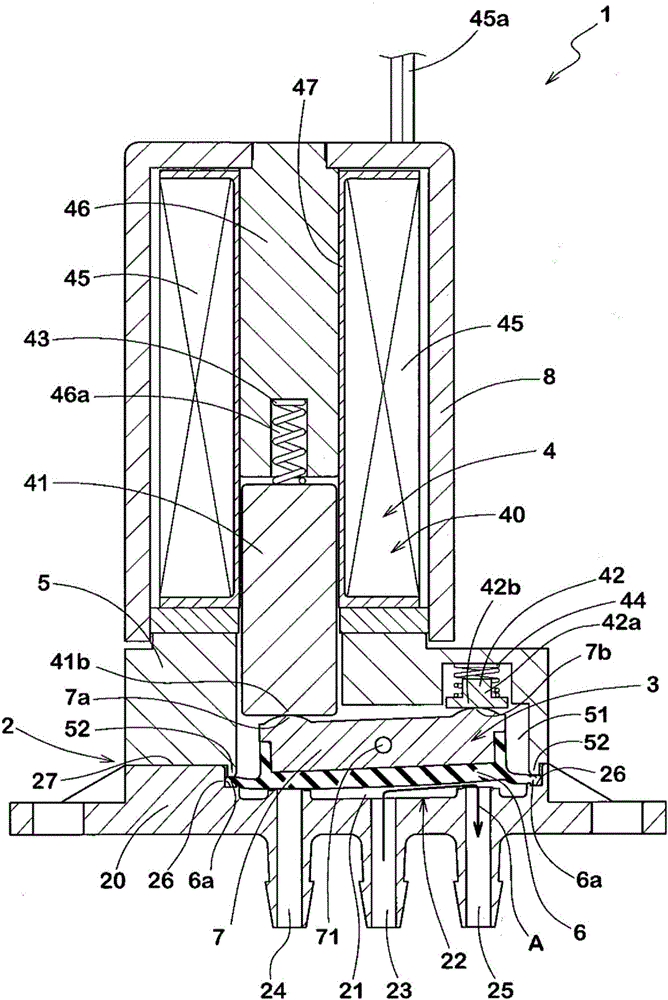
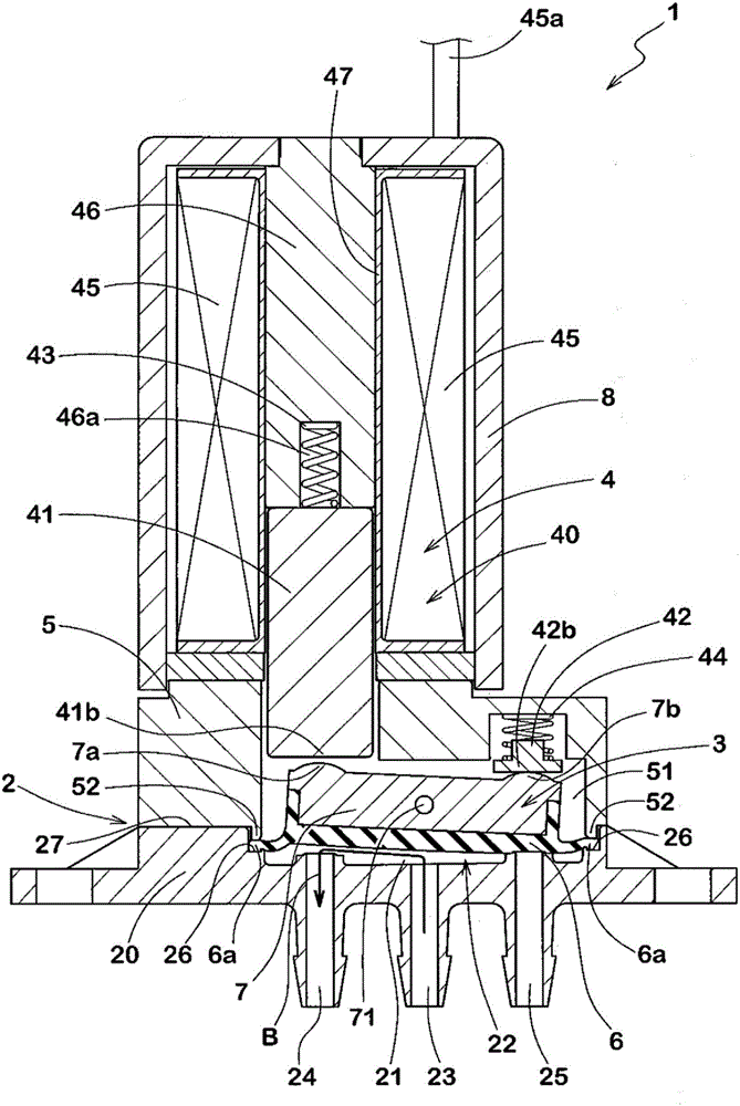
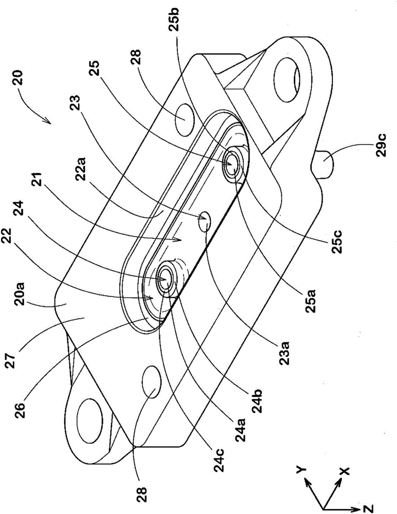
This invention provides a valve device. The valve device (1) has: a valve main body (2) that compartmentalizes a valve chamber (21) provided with an NO outflow port (25) and NC outflow port (24) through which a fluid flows; and a valve body (3) that opens / closes the NC outflow port (24) and NO outflow port (25). The valve body (3) includes: a diaphragm (6) disposed in a manner so as to cover the valve chamber (21); and a drive means (4) that, by means of pressing the diaphragm (6), can open / close the NC outflow port (24) and NO outflow port (25). A first valve seat (24b) and second valve seat (25b) are formed at the periphery of the NC outflow port (24) and NO outflow port (25). The diaphragm (6) comprises an elastic material of which the JIS-K6253 durometer A hardness is A50-A85. The pressure of the seated diaphragm (6) to the first valve seat (24b) and second valve seat (25b) is 0.5-1.0 N / mm<2>.
Description
technical field [0001] The present invention relates to a valve device used in various analysis devices such as chemical inspection devices, environmental analysis devices, and bioengineering research equipment. Background technique [0002] In the above-mentioned various analysis devices, the improvement of measurement accuracy, the improvement of inspection speed, the miniaturization of specimens and reagents, and the miniaturization of devices have become important issues. Therefore, valves that control the flow rate of fluid used in measurement Devices require further improvements in performance. In the valve device described above, in order to achieve superior chemical resistance and the like, a diaphragm made of an elastic rubber material or the like is used as the opening and closing mechanism of the valve. The diaphragm constitutes a partition wall that defines the valve chamber, and receives a driving force from the outside to switch the flow path of the fluid. ...
Claims
Login to View More Application Information
Patent Timeline
 Patent Type & AuthorityApplications(China)
IPC IPC(8): F16K7/12F16K11/24F16K31/06
CPCB01L3/567B01L2400/0622F16K11/022F16K11/052F16K11/0525F16K31/0641F16K31/10F16K31/105Y10T137/86501B01L2300/123B01L2400/0638F16K7/14F16K25/005
Inventor二俣和夫石丸毅森田耕平
OwnerSUMITOMO RUBBER IND LTD