Novel large-lift-force vertical take-off and landing aircraft

A technology for vertical take-off and landing and aircraft, which is used in vertical take-off and landing aircraft, aircraft, rotorcraft, etc. Insufficient maneuverability, reduction of adverse interference, reduction of bending torque

Inactive Publication Date: 2016-08-03
刘行伟
View PDF8 Cites 8 Cited by
  • Summary
  • Abstract
  • Description
  • Claims
  • Application Information

AI Technical Summary

Problems solved by technology

[0005] Ordinary helicopters have vertical take-off and landing capabilities, but do not have the high-efficiency, high-speed level flight capabilities of fixed-wing aircraft. Ordinary fixed-wing aircraft have high-efficiency, high-speed level flight capabilities, but do not have vertical take-off and landing capabilities.

Method used


Image

  • Novel large-lift-force vertical take-off and landing aircraft
  • Novel large-lift-force vertical take-off and landing aircraft
  • Novel large-lift-force vertical take-off and landing aircraft

Examples


Embodiment 1

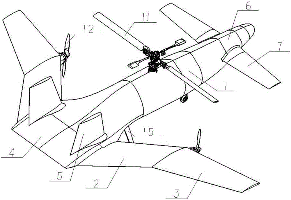
[0031] Embodiments of the present invention provide a novel high-lift vertical take-off and landing aircraft, such as Figure 1~4 As shown, the aircraft includes: a fuselage 1, main wings arranged on both sides of the tail 4 of the fuselage 1, the main wings are formed by the conformal shape of the inner main wing 2 and the outer main wing 3, and the inner main wing 2 is a forward-swept wing, The forward sweep angle is 10°~75°, two vertical tails 5 are arranged above the tail 4 of the fuselage 1, canards 7 are arranged on both sides of the nose 6 of the fuselage 1, and the fuselage 1 A rotor 11 is arranged on the upper side, a power plant 12 is arranged between the inner main wing 2 and the outer main wing 3 , and a landing gear 15 is arranged at the bottom of the fuselage 1 . The rear and forward-swept settings of the inner main wing of the present invention prevent the wing from being in the downwash area of ​​the rotor 11, thereby avoiding the adverse interference of the do...

Embodiment 2

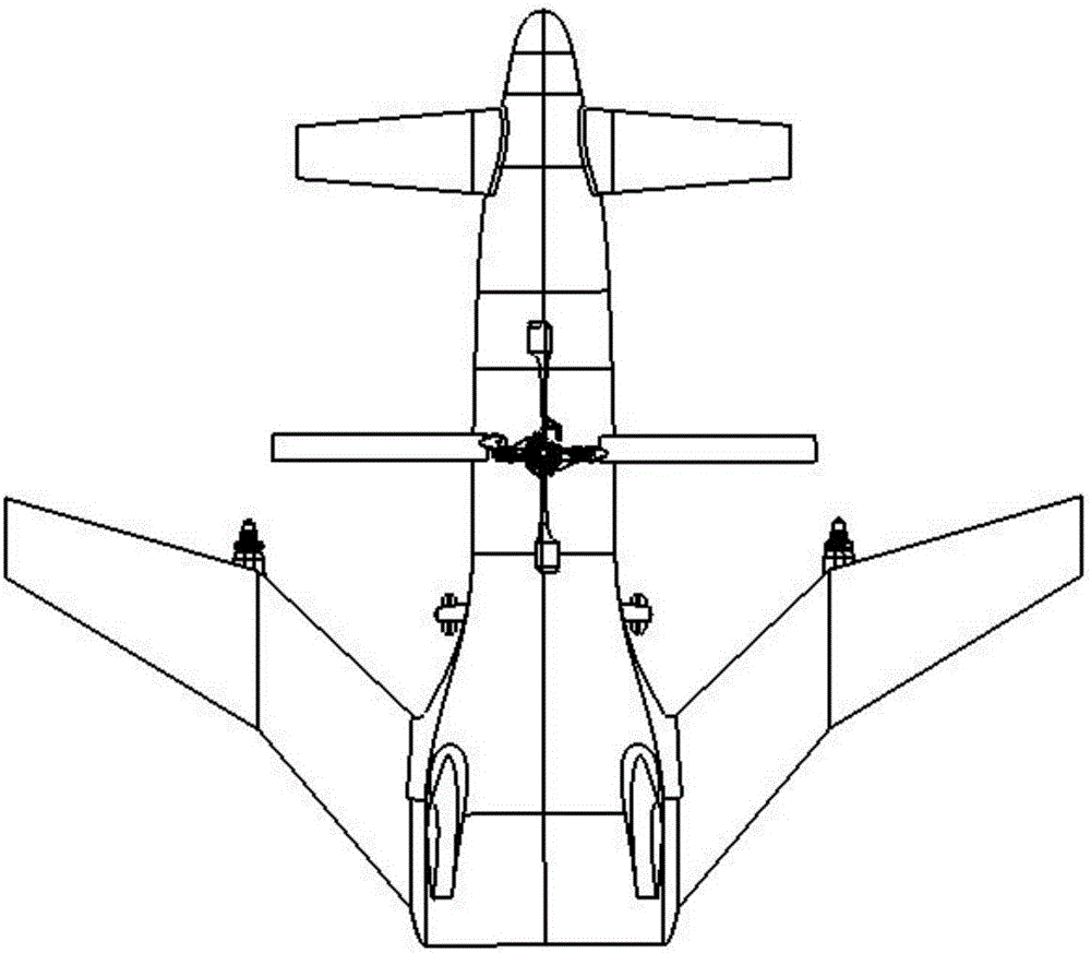
[0035] Embodiments of the present invention provide a novel high-lift vertical take-off and landing aircraft, such as Figure 5 As shown, the aircraft includes: a fuselage 1, main wings arranged on both sides of the tail 4 of the fuselage 1, the main wings are formed by the conformal shape of the inner main wing 2 and the outer main wing 3, and the inner main wing 2 is a forward-swept wing, The forward sweep angle is 10°~75°, two vertical tails 5 are arranged above the tail 4 of the fuselage 1, canards 7 are arranged on both sides of the nose 6 of the fuselage 1, and the fuselage 1 A rotor 11 is arranged on the upper side, a power plant 12 is arranged between the inner main wing 2 and the outer main wing 3 , and a landing gear 15 is arranged at the bottom of the fuselage 1 . The rear and forward-swept settings of the inner main wing of the present invention prevent the wing from being in the downwash area of ​​the rotor 11, thereby avoiding the adverse interference of the down...

Embodiment 3

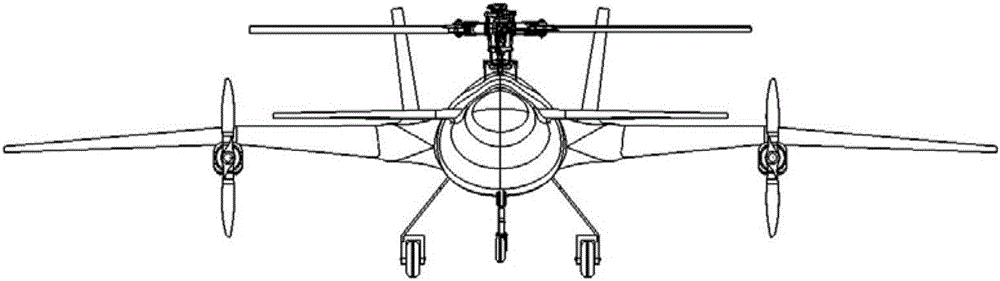
[0040] Embodiments of the present invention provide a novel high-lift vertical take-off and landing aircraft, such as Image 6 As shown, the aircraft includes: a fuselage 1, main wings arranged on both sides of the tail 4 of the fuselage 1, the main wings are formed by the conformal shape of the inner main wing 2 and the outer main wing 3, and the inner main wing 2 is a forward-swept wing, The forward sweep angle is 10°~75°, two vertical tails 5 are arranged above the tail 4 of the fuselage 1, canards 7 are arranged on both sides of the nose 6 of the fuselage 1, and the fuselage 1 A rotor 11 is arranged on the upper side, a power plant 12 is arranged between the inner main wing 2 and the outer main wing 3 , and a landing gear 15 is arranged at the bottom of the fuselage 1 . The rear and forward-swept settings of the inner main wing of the present invention prevent the wing from being in the downwash area of ​​the rotor 11, thereby avoiding the adverse interference of the downw...


PUM


Abstract

The invention discloses a novel large-lift-force vertical take-off and landing aircraft. The aircraft comprises an aircraft body and main wings arranged on the two sides of an aircraft tail of the aircraft body. Each main wing is jointly formed by an inside main wing body and an outside main wing body. Each inside main wing body is a sweep-forward wing, and a sweep-forward angle ranges from 10 degrees to 75 degrees. Two vertical tails are arranged above the aircraft tail of the aircraft body. Canards are arranged on the two sides of an aircraft head of the aircraft body. A rotor wing is arranged above the aircraft body. A power device is arranged between each inside main wing body and the corresponding outside main wing body. An undercarriage is arranged at the lower portion of the aircraft body. By the adoption of the novel large-lift-force vertical take-off and landing aircraft, the flight properties of vertical take-off and landing, the high speed, the long navigation time and the large voyage are considered, the characteristic of a large task load is achieved, and the lift-drag characteristic in the high-speed flight process and the propelling efficiency of a power system are higher than those of a helicopter and those of a tilt rotor, a flight envelope is wider; and meanwhile decoupling is controlled through lift force and horizontal thrust, so that the aircraft is in transition from a low-speed flight state to a high-speed cruising state stably.

Description

technical field [0001] The invention belongs to the field of aircraft design, and in particular relates to a novel high-lift vertical take-off and landing aircraft. Background technique [0002] Vertical take-off and landing aircraft mainly originated from vertical take-off and landing aviation technology, and vertical take-off and landing aviation technology, as the name implies, refers to the aviation technology that aircraft can complete take-off and landing without taxiing. Vertical take-off and landing aviation technology originated in the 1950s. In the world, the United Kingdom, the United States, and Russia have successively adopted this technology on their aircraft carriers. [0003] Aircraft with vertical take-off and landing capabilities do not require special airports and runways, and only need a small flat ground to ensure the safe take-off and landing of the aircraft, which reduces the dependence of the aircraft on airport runways and other facilities, and great...

Claims


Application Information

Patent Timeline
Patent Type & Authority Applications(China)
IPC IPC(8): B64C27/22B64C29/00
CPCB64C27/22B64C29/00
Inventor 刘行伟高超胡旭
Owner 刘行伟
Why Eureka
Try Eureka