One-direction blocking mechanism of roller bed conveyor

A material stop mechanism and conveyor technology, applied in the direction of rollers, transportation and packaging, can solve the problems of difficult control of elastic force, low reliability, easy failure of springs, etc., and achieve the effect of simple structure and long service life

Inactive Publication Date: 2016-08-03
HUANGSHI HUATIAN AUTOMATION EQUIP
View PDF6 Cites 1 Cited by
  • Summary
  • Abstract
  • Description
  • Claims
  • Application Information

AI Technical Summary

Problems solved by technology

[0002] In the roller bed conveyor, according to the process requirements, it is necessary to control the conveying of objects between the roller beds. The objects on the roller bed are transferred to another roller bed for transportation. In order to achieve this purpose, the existing method is to install an elastic pin stopper device on the roller bed. The push rod can press down the elastic pin, but the structure of this elastic pin device is relatively complicated, the elastic force is not easy to control, the spring is easy to fail, and the reliability is not high

Method used


Image

  • One-direction blocking mechanism of roller bed conveyor
  • One-direction blocking mechanism of roller bed conveyor
  • One-direction blocking mechanism of roller bed conveyor

Examples


Embodiment Construction

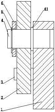
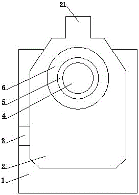
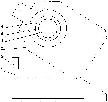
[0009] see Figure 1 to Figure 3 , the present invention includes a seat plate 1, a baffle plate 2, a limit block 3, a rotating shaft 4, a baffle ring 5 and a washer 6, the upper part of the baffle plate 2 is provided with a rectangular stopper 21, and the middle of the rotating shaft 4 is provided with There is an annular boss 41, the right part of the rotating shaft 4 is installed in the hole of the seat plate 1, the baffle plate 2 and the washer 6 are sequentially installed on the left part of the rotating shaft 4 from right to left, and the retaining ring 5 is installed In the annular groove on the left end of the rotating shaft 4, the limit block 3 is installed at the inner position of the left side of the baffle plate 2. The weight of the baffle plate 2 at the lower part of the rotating shaft 4 is heavier than the weight at the upper part of the rotating shaft 4. . An interference fit is adopted between the right part of the rotating shaft 4 and the hole of the seat pla...


PUM


Abstract

The invention discloses a one-direction blocking mechanism of a roller bed conveyor. The one-direction blocking mechanism of the roller bed conveyor comprises a base plate (1), a blocking plate (2), a limiting block (3), a rotary shaft (4), a stop ring (5) and a gasket (6), a rectangular stopper (21) is arranged on the upper portion of the blocking plate (2); an annular boss (41) is arranged on the middle portion of the rotary shaft (4); the right portion of the rotary shaft (4) is installed into a hole of the base plate (1); the blocking plate (2) and the gasket (6) are installed on the left portion of the rotary shaft (4) sequentially from right to left; the stop ring (5) is installed in an annular slot in the left end of the rotary shaft (4); the limiting block (3) is installed in the position, close to the inner side, of the left side face of the blocking plate (2); and the weight of the portion, below the rotary shaft (4), of the blocking plate (2) is larger than that of the portion, above the rotary shaft (4), of the blocking plate (2). The one-direction blocking mechanism of the roller bed conveyor is simple in structure, safe, reliable and long in service life.

Description

technical field [0001] The invention relates to a conveying machine, in particular to a one-way material stopper mechanism of a roller bed conveyor. Background technique [0002] In the roller bed conveyor, according to the process requirements, it is necessary to control the conveying of objects between the roller beds. For example, sometimes it is necessary to block the objects conveyed by the roller beds to prevent the objects from falling, but sometimes it is necessary to move a roller bed. The objects are transferred to another roller bed for conveying. In order to achieve this purpose, the existing method is to install an elastic pin stopper on the roller bed. The push rod can press down the elastic pin, but the structure of the elastic pin device is complicated, the elastic force is not easy to control, the spring is easy to fail, and the reliability is not high. SUMMARY OF THE INVENTION [0003] The purpose of the present invention is to provide a one-way stopper ...

Claims


Application Information

Patent Timeline
IPC IPC(8): B65G13/12
CPCB65G13/12
Inventor 陈朝阳
Owner HUANGSHI HUATIAN AUTOMATION EQUIP
Why Eureka
Try Eureka