
Pneumatic elevator and control method

A technology of pneumatic lifting and control device, which is applied to elevators, elevators in buildings, hoisting devices, etc., can solve the problems of limited use of escalators, easy occurrence of danger, and injury to elevator personnel, and achieves the effect of protecting safety.

Active Publication Date: 2016-08-03
胡津铭
View PDF10 Cites 17 Cited by
  • Summary
  • Abstract
  • Description
  • Claims
  • Application Information

AI Technical Summary

Problems solved by technology

With the development of high-rise buildings, devices for transporting people or goods are also widely used. Common lifting devices in the prior art include escalators, elevators, etc., because escalators take up a lot of space and need to pass through when taking an escalator. Multiple transfers, therefore, the use of escalators is greatly restricted
At present, the most widely used is the elevator. The elevator is mainly composed of a car, a balance system, a traction system and a guiding system. The elevator with this structure will inevitably wear out the mechanical parts after a long period of operation. When the mechanical parts When the mechanical failure occurs due to wear and tear, there may be an incident of falling down the ladder, which is prone to danger
Existing elevators generally use brakes to prevent falling events. When an accident occurs in the elevator, the brakes will be locked to prevent the elevator from falling. When the brake locks suddenly, it may cause injury to the people in the elevator first, and may cause damage to the elevator guide rail and other components at the same time.

Method used


Image

  • Pneumatic elevator and control method
  • Pneumatic elevator and control method
  • Pneumatic elevator and control method

Examples


Embodiment 1

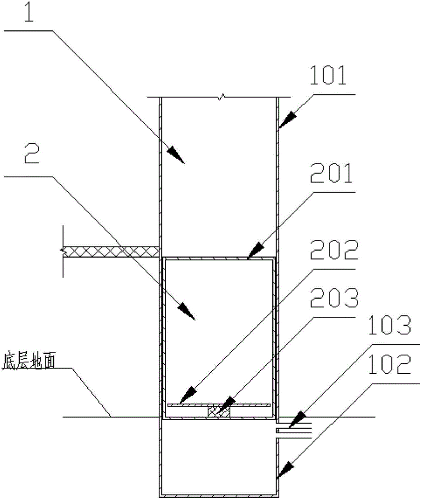
[0043] Such as figure 1 As shown, the pneumatic lift of the present embodiment comprises an elevator shaft 1 with more than two floors, an elevator car 2 running up and down in the elevator shaft, and a control device. The elevator shaft 1 includes an elevator shaft 101 and a buffer shaft 102 integrally arranged. , the buffer shaft 102 is a sealed shaft located at the lower end of the lifting shaft 101; wherein, the upper end of the lifting shaft 101 is provided with an air vent, and the lower end of the lifting shaft 101 is provided with an air discharge port and an air charging port 103, and the discharge port The gas port and the gas charging port 103 are connected with an inflation device and a deflation device; each floor shaft is provided with an airtight elevator door;

[0044] At least the bottom of the elevator car 2 is provided with a sealing section that cooperates with the air seal of the elevator shaft 1 (the air seal here is a relative seal, which allows gas leak...

Embodiment 2

[0052] On the basis of the above-mentioned embodiments, the elevator car 2 includes a car casing 201 and a weighing device arranged at the bottom of the car casing 201, and an air pressure sensor is arranged in the enclosed space, and the air pressure sensor and the weighing device The weight device communicates with the control device, and the control device controls the inflation device and the deflation device according to the data transmitted by the weighing device and the air pressure sensor.

[0053] The weighing device includes a cylindrical pressure sensor 203 arranged at the center of the bottom surface of the car housing 201 and a supporting plate 202 arranged on the cylindrical pressure sensor 203;

[0054] The elevator car 2 of this embodiment is provided with a weighing device. During the process of personnel entering and leaving, the weighing device measures the current load and transmits the load to the control device. The air pressure sensor measures the current...

Embodiment 3

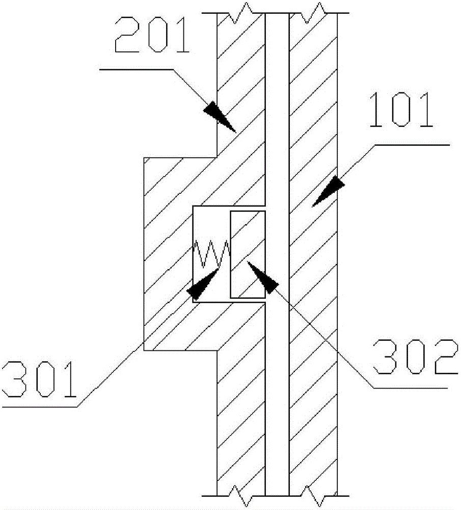
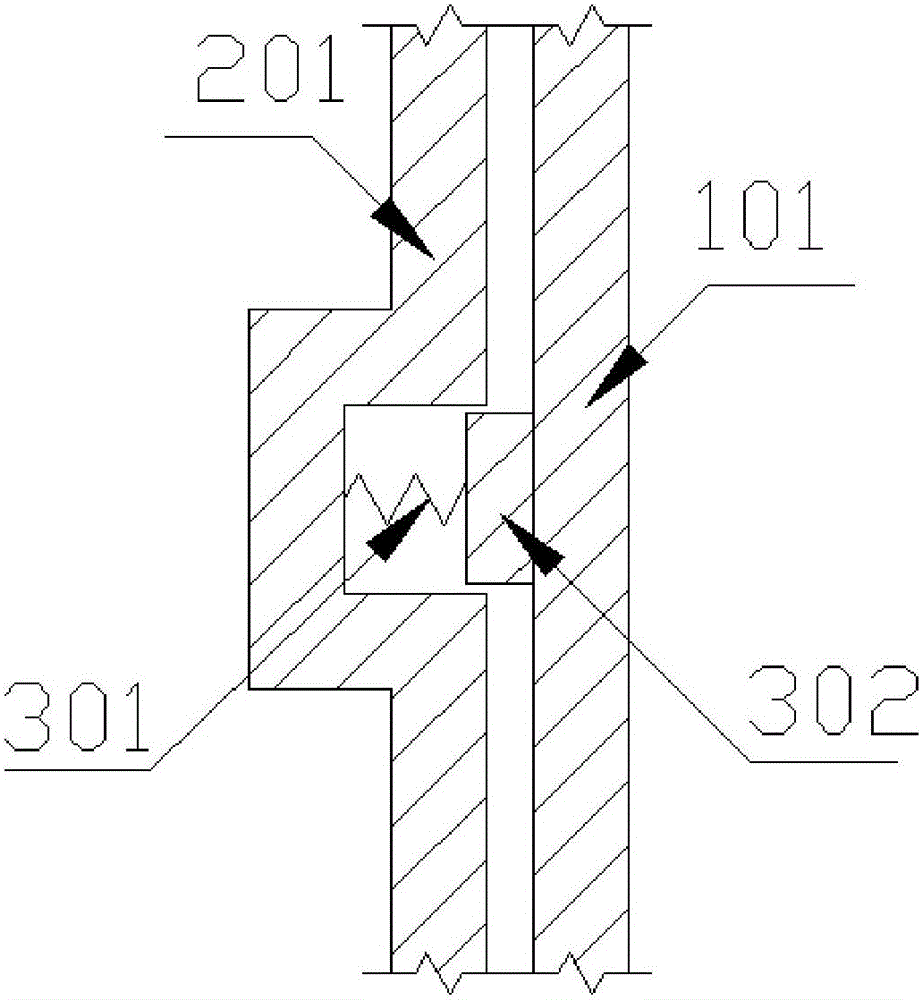
[0058] On the basis of the above examples, if Figure 2~3 As shown, the outside of the elevator car is provided with a braking device, and the position of the elevator shaft corresponding to each floor is provided with a position sensor, the position sensor communicates with the control device, and the control device communicates with the signal of the position sensor Control the braking device.

[0059] The braking device includes several sub-braking devices that are evenly arranged along the circumference of the elevator car 2, and the sub-braking devices include electromagnets, springs 301 and arc-shaped brake pads 302; The box housing 201 is provided with a groove, and one end of the arc-shaped brake piece 302 is hinged in the groove, and the two ends of the spring 301 are respectively connected with the arc-shaped brake piece 302 and the bottom surface of the groove, and the electromagnet It is arranged on the bottom surface of the groove; when the electromagnet is energ...


PUM


Abstract

The invention discloses a pneumatic elevator which is provided for mainly solving the problem that danger is prone to occurring when existing elevators drop. The pneumatic elevator comprises an elevator shaft, an elevator car and a control device. The elevator shaft comprises a lifting shaft body and a buffer shaft body. The buffer shaft body is arranged at the lower end of the lifting shaft body and connected with the lifting shaft body. The lower end of the lifting shaft body is connected with an air inflation device and an air deflation device. The bottom of the elevator car is matched with the elevator shaft in a sealed mode. The space which is located under the bottom of the elevator car in the elevator shaft is an airtight space. When the air inflation device charges air into the airtight space, the elevator car ascends. When the air deflation device deflates the airtight space, the elevator car descends. The control device is used for controlling starting and stopping of the elevator car. By adopting the pneumatic elevator, when the elevator drops, the elevator car cannot collide with other structures rigidly, and the safety coefficient is high.

Description

technical field [0001] The invention relates to a lifting device for transporting people or goods in a building, in particular to a pneumatic lift and a control method. Background technique [0002] As land resources become more and more scarce, the current architectural planning is planned as a high-rise structure. This kind of high-rise structure can maximize the use of limited land resources, and can also use existing resources to create maximum value. With the development of high-rise buildings, devices for transporting people or goods are also widely used. Common lifting devices in the prior art include escalators, elevators, etc., because escalators take up a lot of space and need to pass through when taking an escalator. Multiple transfers, therefore, the use of escalators is greatly restricted. At present, the most widely used is the elevator. The elevator is mainly composed of a car, a balance system, a traction system and a guiding system. The elevator with this s...

Claims


Application Information

Patent Timeline
IPC IPC(8): B66B9/04B66B5/28B66B7/02B66B1/06B66B1/34B66B1/36B66B11/02B66B11/04B66D5/30
CPCB66B1/06B66B1/3484B66B1/3492B66B1/36B66B5/282B66B7/02B66B9/04B66B11/024B66B11/0423B66B2201/215B66D5/30B66D2700/03
Inventor 胡津铭
Owner 胡津铭
Features
  • Generate Ideas
  • Intellectual Property
  • Life Sciences
  • Materials
  • Tech Scout
  • Unparalleled Data Quality
  • Higher Quality Content
  • 60% Fewer Hallucinations
Learn More