Cooling sealing system

A sealing system and sealing device technology, applied in the direction of cooling device, etc., can solve the problems of harmful influence of cooling wall cooling effect, not much improvement, pollution of circulating water of furnace body, etc.

Active Publication Date: 2016-08-03
HUATIAN NANJING ENG & TECH CORP MCC
View PDF5 Cites 4 Cited by
  • Summary
  • Abstract
  • Description
  • Claims
  • Application Information

AI Technical Summary

Problems solved by technology

[0003] This nitrogen + water cooling and sealing form has two problems because the cooling water is mostly discharged directly from the airtight box / distributor and then enters the furnace body drainage groove. On the one hand, the cooling water is in the airtight box / distributor The absorbed dust and impurities will be directly discharged into the furnace tank along with the water, polluting the circulating water of the furnace body. If things go on like this, the change of the cooling water quality of the furnace body will have a harmful impact on the cooling effect of the stave, which is not conducive to the normal production of the blast furnace; On the one hand, in order to seal the high-pressure gas (~0.2MPa) that enters the airtight box / distributor from the blast furnace, a large amount of high-pressure nitrogen needs to be continuously injected into the airtight box / distributor, resulting in a waste of nitrogen resources
In actual design and production application, both designers and production operation technicians have discovered the existence of these two problems, but they have not paid much attention to them, thinking that the water discharged from the airtight box / distributor in a short period of time will not affect production. If the impact is too great, it is okay to consume more nitrogen. Therefore, this situation has continued to this day and has not changed much.

Method used


Image

  • Cooling sealing system

Examples


Embodiment 1

[0023] In this embodiment, the cooling and sealing system is described by taking the airtight box / distributor applied to the top charging equipment of a blast furnace as an example.

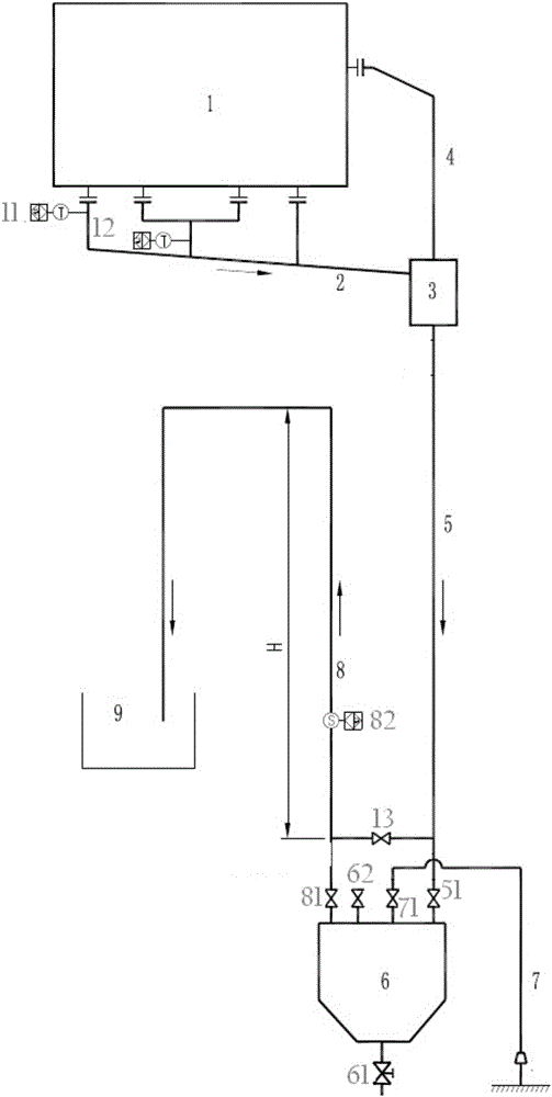
[0024] The cooling and sealing system of this embodiment includes an air-water separation device and a U-shaped sealing device sequentially arranged between the water outlet of the air-tight water-cooling equipment 1 of the air-tight box / distributor and the drainage tank 9 .

[0025] The gas-water separation device includes a water outlet pipe 12 connected to an airtight water-cooled water outlet, a water outlet main pipe 2 , a gas-water separation tank 3 and an air return pipe 4 , and also includes a temperature detection device 11 arranged on the water outlet pipe 12 . The water outlet pipe 12 of the cooling water is connected to the water outlet main pipe 2, and communicates with the gas-water separation tank 3 through the water outlet main pipe 2, and the air return pipe 4 connects the air out...

Embodiment 2

[0035] The cooling and sealing system of this embodiment improves the U-shaped pipeline system on the basis of Embodiment 1, and realizes the sewage discharge, water replenishment and cleaning of the sedimentation tank 6 without affecting the work of the system.

[0036] In the cooling and sealing system of this embodiment, a connecting pipe is arranged between the inlet pipe 5 of the sedimentation tank and the return pipe 8, and a connecting valve 13 is arranged on the connecting pipe; the inlet pipe 5 of the sedimentation tank and the return pipe On 8, switch valves 51 and 81 are respectively arranged downstream of the communication pipe, a blowdown valve 61 is arranged at the bottom end of the sedimentation tank 6, and an exhaust valve 62 is arranged at the upper end of the sedimentation tank.

[0037] In order to clean the settling tank 6, the settling tank 6 is also connected with a water replenishment device, and the water replenishment device includes a water replenishme...


PUM


Abstract

The invention discloses a cooling sealing system mainly designed for reducing losses of an airtight water cooling system of a high-temperature and high-pressure device. The cooling sealing system comprises an air-water separation device and a U-shaped sealing device which are sequentially arranged between an airtight water cooling device and a drainage groove. The U-shaped sealing device comprises a settling tank arranged at the lowest point, a settling tank water inlet pipe and a settling tank water return pipe, wherein the settling tank water inlet pipe and the settling tank water return pipe communicate with the settling tank and are arranged above the settling tank. According to the cooling sealing system, on the basis of traditional extensive type design, the design improvement and innovation are made on a water outlet system of the airtight water cooling device. On one hand, cooling water is cyclically utilized after being purified, water consumption is reduced, the quality of circulating water is guaranteed, and the long service life of a blast furnace is facilitated; and on the other hand, after the system normally runs, the pressure of gas in a cooled device can be controlled by adjusting the elevation of the water return pipe, and therefore the consumption of high-pressure gas is reduced.

Description

technical field [0001] The invention relates to the field of cooling equipment, in particular to a cooling and sealing system suitable for cooling and sealing high-temperature and high-pressure equipment in an airtight and water-cooled form. Background technique [0002] At present, the cooling system used for the airtight box / distributor in the top charging equipment of the blast furnace is mostly in the form of nitrogen + water cooling and sealing, and the nitrogen is mainly used for sealing inside the airtight box / distributor. Prevent the blast furnace gas in the airtight box / distributor from overflowing; the main function of the water in it is to physically cool the transmission mechanism in the airtight box / distributor. Judging by the temperature of the outlet cooling water. [0003] This nitrogen + water cooling and sealing form has two problems because the cooling water is mostly discharged directly from the airtight box / distributor and then enters the furnace body d...

Claims


Application Information

Patent Timeline
Patent Type & Authority Applications(China)
IPC IPC(8): C21B7/10
CPCC21B7/10
Inventor 周飞高成云程长生王磊
Owner HUATIAN NANJING ENG & TECH CORP MCC
Why Eureka
Try Eureka