
Method of monitoring yarn quality in optical scanner of yarn quality and optical scanner for implementing same

An optical detector and yarn quality technology, which is applied in the direction of material analysis through optical means, scientific instruments, and the use of optical devices, can solve the problems of different sensitivities and differences in individual optical components

Active Publication Date: 2016-08-03
RIETER CZ AS
View PDF4 Cites 3 Cited by
  • Summary
  • Abstract
  • Description
  • Claims
  • Application Information

AI Technical Summary

Problems solved by technology

[0011] A disadvantage of the above solution is the fact that individual optical elements may differ in sensitivity and may generate different analog values ​​for falling light of the same energy

Method used


Image

  • Method of monitoring yarn quality in optical scanner of yarn quality and optical scanner for implementing same
  • Method of monitoring yarn quality in optical scanner of yarn quality and optical scanner for implementing same
  • Method of monitoring yarn quality in optical scanner of yarn quality and optical scanner for implementing same

Examples


Embodiment Construction

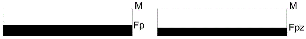
[0023] figure 2 Unsaturated and fully irradiated optics are shown, where the black color corresponds to the amount of energy falling on the optic. Due to the fact that it is an optical element with an analog output, this optical element must not saturate even during the maximum illuminance of the radiation source. M is the maximum value of the analog signal that can be provided by the optical element at its output if the optical element is illuminated with such intense light that it will be in so-called saturation. Fv is the resulting value of the simulated signal provided by an individual fully irradiated optical element not shaded by the yarn. The figure on the right shows the same optic partially obscured by yarn, where Fp is the output value of the analog signal during partial shading by the yarn. The energy loss caused by the partial shading of the optical element by the yarn is determined by the difference Fv - Fp.

[0024] However, it must be taken into account th...


PUM


Abstract

Yarn quality is monitored by means of a line optical sensor in an optical scanner of yarn quality, the line optical sensor comprising one or two lines of separate optical elements of rectangular form, which provide on their output an analog signal that is proportional to the stage of their illumination. The analog signals of all the separate optical elements illuminated by a radiation source and that of the unshielded yarns are scanned for each separate optical element and in all the operation modes of the quality optical scanner, and stored into an electronic memory as initial (Fc1), operational (Fc2) or working values (Fc3) of the separate optical elements according to preliminary defined criteria. These values are then subsequently compared with the aim to judge correct function of the sensor and to eliminate production and operational faults and failures. The invention further discloses the optical scanner for implementing the above method.

Description

technical field [0001] The invention relates to a method for monitoring yarn quality in an optical detector of yarn quality by means of a linear optical sensor comprising one or two rows of individual rectangular-shaped optical elements whose output An analog signal proportional to the irradiance of the optical element is provided at the end. [0002] The invention also relates to an optical detector for carrying out the method according to the invention, comprising a sensor with a plurality of optical elements arranged next to each other in one or two rows, for the The image of the yarn is projected vertically onto the individual optical elements of the sensor to monitor the parameters of the moving yarn on the textile machine. Background technique [0003] Optical detectors of the yarn quality are used on textile machines during the production of the yarn, and in principle it is not possible to protect them from contamination by dust or yarn residues, and it is therefore ...

Claims


Application Information

Patent Timeline
Patent Type & Authority Applications(China)
IPC IPC(8): D01H13/32D01H1/16G01B11/10
CPCD01H13/165D01H13/32G01B11/105G01N21/8903G01N21/8915G01N33/365D01H13/22
Inventor P.考萨里克Z.伯兰
Owner RIETER CZ AS
Learn More