Ballastless track stiffness adjustment device

A technology of adjusting device and ballastless track, which is applied to bridge parts, bridges, buildings, etc., can solve the problems of reducing structural performance, shortening the life of ballastless track stiffness adjusting device, and noise beam damage.

Active Publication Date: 2017-06-16
CENT SOUTH UNIV +1
View PDF7 Cites 0 Cited by
  • Summary
  • Abstract
  • Description
  • Claims
  • Application Information

AI Technical Summary

Problems solved by technology

[0004] (1) It cannot provide enough headroom for beam body rotation and vertical displacement: long-span bridges produce large corners or vertical displacements under the action of train load or temperature, while pure steel or pure concrete structures have a large section height, and The bottom surface of the main board is flat, which causes the interaction or collision between the bridge girder and the main board to generate a large internal force and reduce the structural performance
[0005] (2) Does not conform to the mechanical characteristics of the structure: the concrete material is a kind of strong pressure and weak tension material. Under the action of load, the top of the main board of the ballastless track stiffness adjustment device is under compression and the bottom is under tension, resulting in a large number of cracks at the bottom, shortening the ballastless track The life of the stiffness adjustment device increases the number of structural maintenance
[0006] (3) The noise pollution of the steel structure is serious: if the ballastless track stiffness adjustment device in the form of pure steel is used, due to the small stiffness, the deformation will be large under the action of the dynamic load of the train, and the macroscopic performance is that the two ends of the main board collide with the beam body repeatedly to generate serious noise and aggravate beam damage
[0007] (4) Structural form: If the ballastless track stiffness adjustment device in the form of pure concrete is used, the corresponding main board is thick and the structural form is not flexible. Formwork pouring and steel bars are required to be made during production. The construction quality is not easy to guarantee and the installation is inconvenient
[0008] (5) Limiting defects: If the horizontal and vertical limit requirements are simply achieved through the protruding structure, the track plate will be worn by the serpentine movement of the train or the action of shaking the head. In severe cases, the track plate will be deformed and the train will derail, which will increase maintenance. workload
[0009] (6) Concrete pouring defects of the ballastless track stiffness adjustment device: the track slab structure is very flat, and the ballastless track stiffness adjustment device needs to be connected with the front and rear track slabs to meet the elevation requirements of the top surface of the rail
Concrete often cannot be vibrated and compacted in a small space, and the quality of the concrete cannot be guaranteed
[0010] Especially in long-span bridges, there are usually large beam gaps, resulting in increased stress on rails and fasteners

Method used


Image

  • Ballastless track stiffness adjustment device
  • Ballastless track stiffness adjustment device
  • Ballastless track stiffness adjustment device

Examples


Embodiment Construction

[0084] The technical content of the present invention will be further described below, but it is not intended to limit the essence of the present invention.

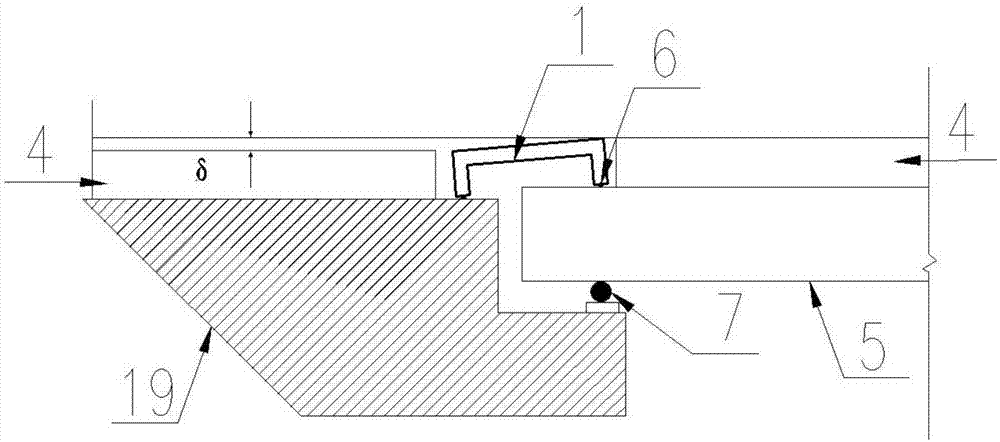
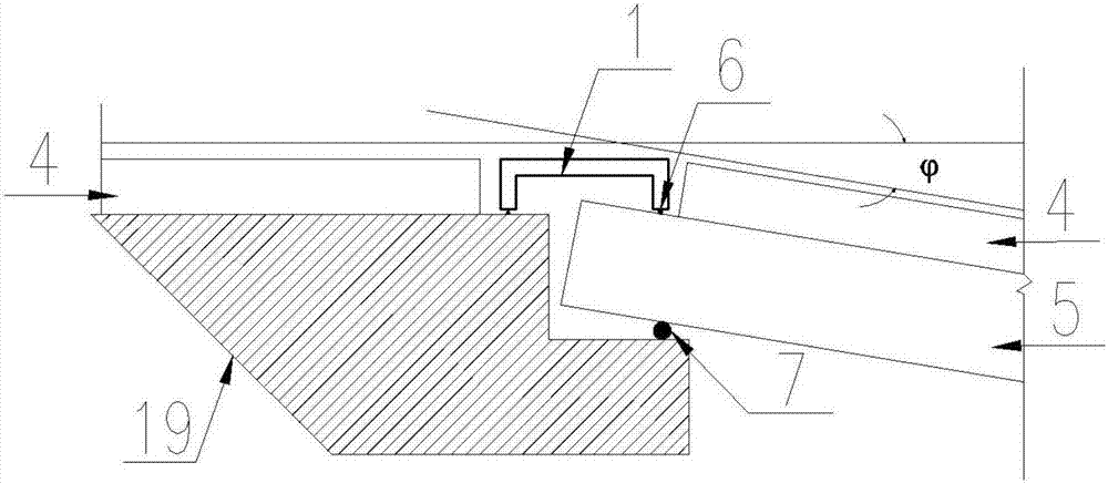
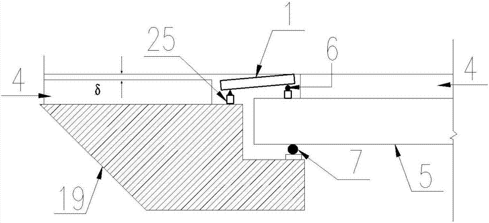
[0085] figure 1 It is one of the structural schematic diagrams of the ballastless track stiffness adjusting device according to the embodiment of the present invention; figure 2 It is the second structural diagram of the ballastless track stiffness adjusting device according to the embodiment of the present invention; image 3 It is the third structural diagram of the ballastless track stiffness adjusting device according to the embodiment of the present invention; Figure 4 It is the fourth structural diagram of the ballastless track stiffness adjusting device according to the embodiment of the present invention; Figure 5 It is the fifth structural diagram of the ballastless track stiffness adjusting device according to the embodiment of the present invention; Image 6 It is a structural schematic diagram of a stee...


PUM


Abstract

The invention discloses a ballastless track rigidity adjusting device. The device comprises a pier, an abutment arranged on a roadbed, beams arranged on the pier, a track board laid on the abutment and the beams, and a steel rail fixed to the track board through fasteners, wherein the track board is disconnected at the portions where the abutment is combined with the beams or at the portions where every two adjacent beams are combined, and minitype supporting bridges used for regulating the beam end rotation angle and vertical stagger of the beams so as to reduce the pull-up force on the fasteners to guarantee the travel safety and stability of a train are arranged between the portions, formed after disconnection, of the track board. The requirements of train load, temperature load, beam deflection and beam flexibility for the structure are met, and the section depth of a main board is reduced remarkably so as to be matched with the height of the flat track board conveniently; meanwhile, the head room between the bottom surface of the main board and top surface of each beam is enlarged, so that enough clearance is provided for rotation and vertical displacement of the beams, the influence of beam deformation on the structure of the track board is reduced, the pull-up force on the fasteners is reduced, and the travel safety of the train and the comfort level of passengers are guaranteed.

Description

technical field [0001] The invention relates to the technical field of high-speed railway bridge structures, in particular to a ballastless track stiffness adjustment device used in a ballastless track bridge system to reduce the influence of beam deformation on the track slab structure. Background technique [0002] High-speed railway construction is an inevitable trend in the development of my country's railway transportation. As my country's high-speed railway construction is gradually implemented and put into operation, ballastless track is used as the main high-speed railway due to its high smoothness, stability and less maintenance times. One of the track structure types. In order to meet the smoothness and stability requirements of high-speed railway lines, it may be necessary to build viaducts for several kilometers or even tens of kilometers. Taking the Beijing-Shanghai high-speed railway as an example, there are 244 bridges, accounting for 80.47% of the length of t...

Claims


Application Information

Patent Timeline
Patent Type & Authority Patents(China)
IPC IPC(8): E01D19/12E01D19/04E01D19/00
CPCE01D19/00E01D19/04E01D19/12
Inventor 谈遂余志武吴玲玉
Owner CENT SOUTH UNIV
Why Eureka
Try Eureka