Constant force float auxiliary flushing time control valve

A float and constant force technology, used in flushing equipment with water tanks, water supply devices, buildings, etc., can solve the problems of fragile valves and sanitary wares that cannot be used normally, and achieve the effect of improving the use function, saving space and optimizing the valve structure.

Active Publication Date: 2016-08-03
GUANGDONG HEGII SANITARY WARES CO LTD
View PDF5 Cites 5 Cited by
  • Summary
  • Abstract
  • Description
  • Claims
  • Application Information

AI Technical Summary

Problems solved by technology

Either the battery needs to be replaced regularly or the electrical appliance needs to be repaired due to degenera

Method used


Image

  • Constant force float auxiliary flushing time control valve

Examples


Embodiment Construction

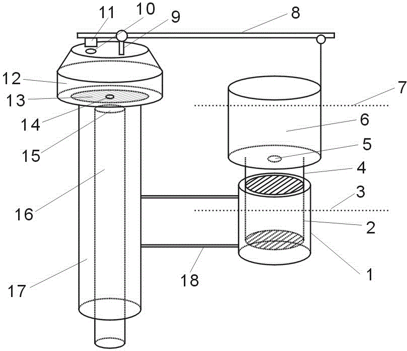
[0020] figure 1 The specific implementation manner of the constant force float assisted flushing time control valve of the present invention is shown. Regardless of whether the water tank is full of water at the high water level 7 or at the low water level 3 after flushing, there is always water in the water storage cup 1, and the constant pressure float 2 in the water storage cup 1 always has buoyancy through the lever arm 8 by blocking 11 Pressure relief hole 10 is sealed. Tap water goes to sealing port 15 through water inlet pipe 16, and the water that pressure guide hole 14 comes in makes the pressure of equal pressure chamber 12 and tap water network pressure equate, between inlet pipe 16 and outlet pipe 17 by spring pressure film 13 self intrinsic elastic seal. The top of the constant force float 2 is connected with the water storage chamber 6 by a connecting rod 4 . The lower part of the water storage chamber 6 is designed with an adjustment hole 5 . There is a fulcr...


PUM


Abstract

The invention discloses a constant force float auxiliary flushing time control valve, which comprises: a water cup, a constant force float, a low water level line, a connecting rod, an adjustment hole, a water storage chamber, a high water level line, a lever arm, a fulcrum, a pressure relief Holes, blockages, equal pressure chambers, spring pressure membranes, pressure guide holes, sealing ports, water inlet pipes, water outlet pipes, and fixed brackets, use the buoyancy of the constant force float in the water cup to close the pressure relief holes, which solves the unreasonable structure of the current flushing valve , Unstable performance and problems that cannot be widely used.

Description

technical field [0001] The invention relates to a sanitary ware valve, in particular to a constant force float assisted flushing time control valve which uses the buoyancy of the constant force float in the water cup to close the pressure relief hole. Background technique [0002] It has been 500 years since the birth of sanitary ware in Britain, and it was introduced to China in the late Qing Dynasty, and it also has a history of more than 100 years. In this long history, people have been exploring in many disciplines such as aesthetics, structural mechanics and ergonomics, and the quantity and quality of products have developed rapidly. However, this industry is still a traditional labor-intensive industry, especially in the optimization of flushing function, there has been no breakthrough progress. For example: how to use the pressure of the tap water network to help wash and replace, it is still almost blank on ordinary products. [0003] All of our sanitary ware are d...

Claims


Application Information

Patent Timeline
IPC IPC(8): E03D1/35
Inventor 谢伟藩段鳗珊
Owner GUANGDONG HEGII SANITARY WARES CO LTD
Why Eureka
Try Eureka