Molybdenum alloy glass detection device with gear rotary table, aperture camera shooting assembly and bearing corner clamping plates

A technology of glass detection and molybdenum alloy, which is applied in the direction of measuring devices, testing material strength and instruments using one-time impact force, which can solve the problems of glass fragments splashing, operator injury, tape collapse, etc. Splash damage, easy to remove effect

Inactive Publication Date: 2016-08-03
WENZHOU ECONOMIC TECH DEV ZONE BINHAI XIONGJIE ELECTROMECHANICAL RES & DEV STUDIO
View PDF4 Cites 4 Cited by
  • Summary
  • Abstract
  • Description
  • Claims
  • Application Information

AI Technical Summary

Problems solved by technology

Chinese patent application number: 2009203050079, tempered glass falling ball test bench, in order to solve the problem of glass fragments splashing everywhere when tempered glass is used for experiments, the method of supporting the frame box is adopted. Although the glass fragments can be collected effectively, it is inconvenient to read the glass fragments. , and the installation efficiency of continuous multi-piece tempered glass is low
Due to the diversity of automobile designs, the glass on the corresponding car is becoming

Method used


Image

  • Molybdenum alloy glass detection device with gear rotary table, aperture camera shooting assembly and bearing corner clamping plates
  • Molybdenum alloy glass detection device with gear rotary table, aperture camera shooting assembly and bearing corner clamping plates
  • Molybdenum alloy glass detection device with gear rotary table, aperture camera shooting assembly and bearing corner clamping plates

Examples


Embodiment Construction

[0063] Describe the present invention in detail below in conjunction with accompanying drawing and specific embodiment:

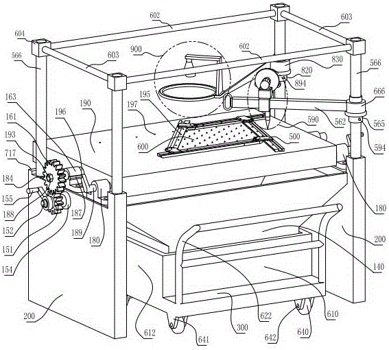
[0064] figure 1 Among them, the bearing corner splint assembly 500 is placed on the test turntable 190, and the trapezoidal glass plate 600 is fixed, the aperture camera assembly 900 is not working when it moves outward, the rotary impactor 590 is located directly above the trapezoidal glass plate 600, and the rotary impactor 590 is in working condition.

[0065] figure 2 Among them, the bearing corner splint assembly 500 is placed on the test turntable 190, and the trapezoidal glass plate 600 is fixed, the rotary impactor 590 is transferred out of the test turntable 190 and is in a non-working state, and the aperture camera assembly 900 is located directly above the trapezoidal glass plate 600 and is in a working state.

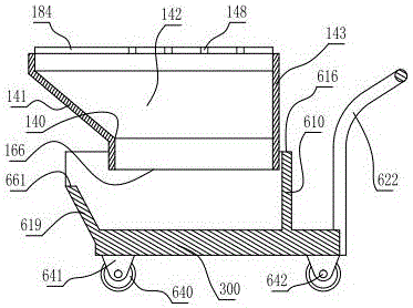
[0066] image 3 In the process, the two sides of the bearing corner splint assembly 500 are removed, the test turntable 190 is in a t...


PUM

PropertyMeasurementUnit
Thicknessaaaaaaaaaa
Depthaaaaaaaaaa
Bottom widthaaaaaaaaaa

Abstract

The invention relates to a tempered glass test and check device, in particular to a molybdenum alloy glass detection device with a gear rotary table, an aperture camera shooting assembly and bearing corner clamping plates. A bearing corner clamping plate assembly is fixed on the upper plane of a test rotary table; a rotary impactor is slidably fixed to an impact cross rod; as an improvement, a transmission gear matches with a manual gear; the manual gear is rotatably fixed to a manual wheel shaft; a shaft clamp spring blocks the outer side surface of the manual wheel shaft; a hand wheel cross rod is fixedly connected to the stepped circle of a hand wheel; a hand wheel crank handle is further arranged at the outer end of the hand wheel cross rod; the transmission gear is fixed to a gear section of a rotary shaft; an aperture camera shooting oblique long handle is arranged on an aperture camera shooting rotary plate of the aperture camera shooting assembly; a horizontal aperture frame and a vertical cross arm camera shooting frame are arranged at the outer lower end of the aperture camera shooting oblique long handle; a camera end is arranged at the upper outer end of the vertical cross arm camera shooting frame; an industrial camera is arranged on the lower front surface of the camera end; and a round fluorescent tube is arranged on the horizontal aperture frame. By applying the rotary impactor, the hammer driving force each time is consistent and crushing tests are ensured to be normalized and unified.

Description

technical field [0001] The invention relates to a tempered glass test and inspection device, in particular to a test and inspection device equipped with an aperture camera assembly instead of a manually operated gear turntable aperture camera bearing corner splint molybdenum alloy glass inspection device. Background technique [0002] G0rd0nGaileG published an article "AutomatedGlassFragmentati0nAnalysis" in 1996, which discussed the detection algorithm of glass fragments. This document involves two key technologies: (1) image acquisition technology. Under a piece of photosensitive paper imaged by glass shards, light sources were applied from two different angles, and an original digital image of the shadow of the crack line of the shards was collected. In this way, due to the use of light sources at different angles, the two images collected must be different. In one of the images, the position of the inconspicuous seam line due to lighting may be more obvious in the oth...

Claims


Application Information

Patent Timeline
IPC IPC(8): G01N3/06G01N3/30G01N3/04G01N3/02
CPCG01N3/02G01N3/04G01N3/068G01N3/30G01N2203/0278G01N2203/04G01N2203/0647
Inventor 陈丹青
Owner WENZHOU ECONOMIC TECH DEV ZONE BINHAI XIONGJIE ELECTROMECHANICAL RES & DEV STUDIO
Why Eureka
Try Eureka