

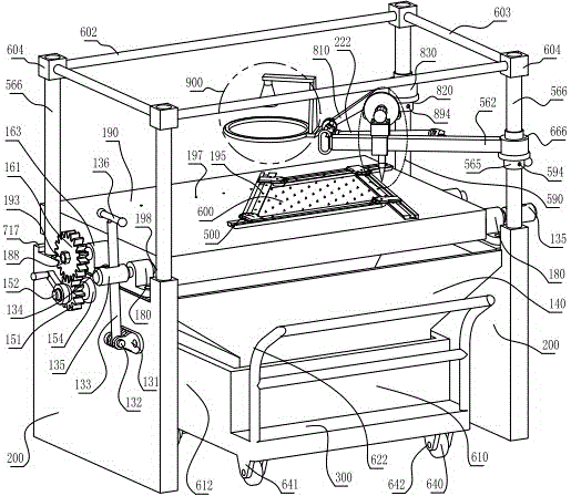
Glass detection rack with gears, light rings, linkage photography functions, chromium alloy wheels, slide rails and corner fixtures
A corner jig, glass detection technology, applied in the direction of measuring device, using a single impact force to test the strength of materials, instruments, etc., can solve the problems of operator injury, non-square, non-uniform, etc., to facilitate removal, improve operation efficiency, ensure normative effect
- Summary
- Abstract
- Description
- Claims
- Application Information
AI Technical Summary
Problems solved by technology
Method used
Image

Examples
Embodiment Construction
[0060] Describe the present invention in detail below in conjunction with accompanying drawing and specific embodiment:
[0061] In Fig. 1, the wheel slideway corner fixture assembly 500 is fixed on the test bench 190, the trapezoidal glass plate 600 is fixed on the wheel slideway corner fixture assembly 500, and the rotary impactor 590 is located directly above the trapezoidal glass plate 600 and is in working condition.
[0062] In FIG. 3 , the rotary impactor 590 is out of operation directly above the trapezoidal glass plate 600 , and the halo camera assembly 900 is located directly above the trapezoidal glass plate 600 and is in a working state.
[0063] In FIG. 5 , the two sides of the wheel slide corner fixture assembly 500 are removed, and the test platform 190 is in a tilted state, which facilitates removal of glass fragments after the trapezoidal glass plate 600 is crushed.
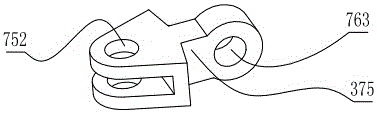
[0064] The camera universal joint and the impact universal joint at both ends of the linkage ...
PUM
| Property | Measurement | Unit |
|---|---|---|
| depth | aaaaa | aaaaa |
| width | aaaaa | aaaaa |
| width | aaaaa | aaaaa |
Abstract
Description
Claims
Application Information