Transmission line comprehensive fault location method for intelligent substations

A technology for smart substations and transmission lines, which can be applied to fault locations, fault detection by conductor type, information technology support systems, etc.

Inactive Publication Date: 2016-08-03
STATE GRID GASU ELECTRIC POWER RES INST +3
View PDF4 Cites 5 Cited by
  • Summary
  • Abstract
  • Description
  • Claims
  • Application Information

AI Technical Summary

Problems solved by technology

Among them, the impedance method assumes that the current at the fault point and the fault component current at the measurement point are in the same phase to obtain a definite solution. This method is easily affected by the system operation mode and load current; the method of solving differential equations is easily affected by high transition resistance; the method of solving complex equations in The left and right ends of the voltage equation are respectively multiplied by the conjugate complex number of the fault component current at the measuring end, and then the imaginary part of the equation is taken to obtain the fault distance. When the impedance angles of the systems on both sides differ greatly or the line is overloaded, a large error will occur; solution two The quadratic equation method supplements the definition of zero-sequence or positive-sequence current distribution coefficient expression of the measurement point into the voltage equation and obtains a quadratic equation about the fault distance. Problem: The loop current method assumes that the opposite side system is an infinite system, and the opposite side bus voltage remains unchanged after a fault. The calculation amount of the method is small, but the assumption conditions are too ideal
[0004] To sum up, several power frequency ranging methods commonly used at present adopt different simplified assumptions, all of which have systematic errors. The error will show different characteristics with the change of fault conditions and operating parameters

Method used


Image

  • Transmission line comprehensive fault location method for intelligent substations
  • Transmission line comprehensive fault location method for intelligent substations
  • Transmission line comprehensive fault location method for intelligent substations

Examples


Embodiment Construction

[0031] Below in conjunction with accompanying drawing and specific embodiment the present invention is described in further detail:

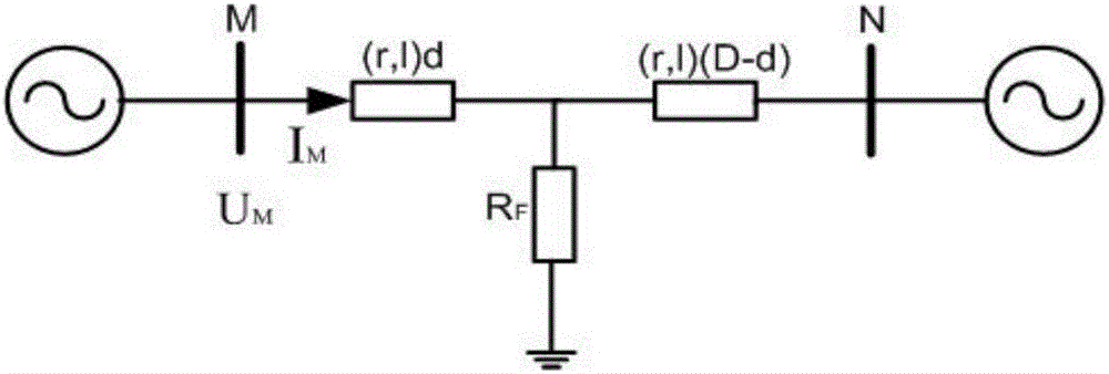
[0032] Taking the Beijing-Tianjin-Tangtang 500kV transmission line as an example, a single-phase ground fault model of the Beijing-Tianjin-Tangzhou 500kV three-phase transmission line through the transition resistance is established, as follows: figure 1 As shown, the line length is D = 300km; the line parameters are r1 = 0.02083Ω / km, l1 = 0.8984mH / km, r0 = 0.1148Ω / km, l1 = 2.2886mH / km, and the variation range of the power supply amplitude on both sides is 0.95 times to 1.05 times the rated voltage, the change range of the phase is 0° to 180°, the change range of the zero-sequence and positive-sequence impedance angle of the opposite end system is 50° to 89°, and the change range of the transition resistance is 0Ω to 200Ω, Change the seven parameters respectively, use 5 kinds of single-ended power frequency ranging methods for ranging, and obtai...


PUM


Abstract

The invention discloses a transmission line comprehensive fault location method for intelligent substations. When a transmission line fails, a method of highest ranging accuracy is selected from the existing single-end power-frequency ranging methods to give accurate fault position information. The existing power-frequency ranging methods have different system error sources, and the ranging accuracy is affected by the power source, the impedance of an opposite-end system, the transition resistance and other parameters. Thus, under different fault conditions, the methods differ in ranging accuracy, and the ranging results are different. According to the method, a large number of training samples during failure of a transmission line are acquired first, the attribute of the training samples is reduced based on the rough set theory, the internal relation between the ranging accuracy and fault conditions is found out, and less influencing parameters are deleted to speed up the solving process. When a system fails, a method achieving a most accurate ranging result is found from a variety of power-frequency ranging methods using a KNN algorithm. Therefore, the ranging accuracy is improved effectively.

Description

technical field [0001] The invention belongs to the technical field of transmission line fault location, and in particular relates to a comprehensive fault location method for transmission lines facing intelligent substations. Background technique [0002] Accurate fault location and timely repair of transmission lines are of great significance to quickly find the fault point and ensure the safe and stable operation of the power grid. The high precision of traveling wave ranging makes it the main method for fault location of transmission lines in my country. However, with the popularization and application of intelligent digital substation technology, especially the use of electronic transformers, the acquisition of traveling wave signals is due to the electronic transformer The limitation of the sampling frequency of the acquisition unit (4kHz) makes it difficult to apply the traveling wave positioning method to the digital smart substation. In this regard, there are curren...

Claims


Application Information

Patent Timeline
Patent Type & Authority Applications(China)
IPC IPC(8): G01R31/08
CPCG01R31/085Y04S10/52
Inventor 姚旭康小宁程蓉智勇崔力心倪赛赛陈新赵杰拜润卿赵毅王春光梅姚张坤贤张大伟郭文科王永年刘巍
Owner STATE GRID GASU ELECTRIC POWER RES INST
Why Eureka
Try Eureka