Reference plane determination method and determination system

A technology of reference plane and determination method, applied in image analysis, image enhancement, instruments, etc., can solve problems such as affecting user experience, virtual objects cannot be matched with real scenes in real time, etc., to achieve the effect of wearable portability and freedom

Inactive Publication Date: 2016-08-03
BOE TECH GRP CO LTD
View PDF3 Cites 5 Cited by
  • Summary
  • Abstract
  • Description
  • Claims
  • Application Information

AI Technical Summary

Problems solved by technology

[0004] In order to solve the above problems, the present invention provides a method and a system for determining a reference plane, which are used to solve the pr

Method used


Image

  • Reference plane determination method and determination system
  • Reference plane determination method and determination system
  • Reference plane determination method and determination system

Examples


Embodiment 1

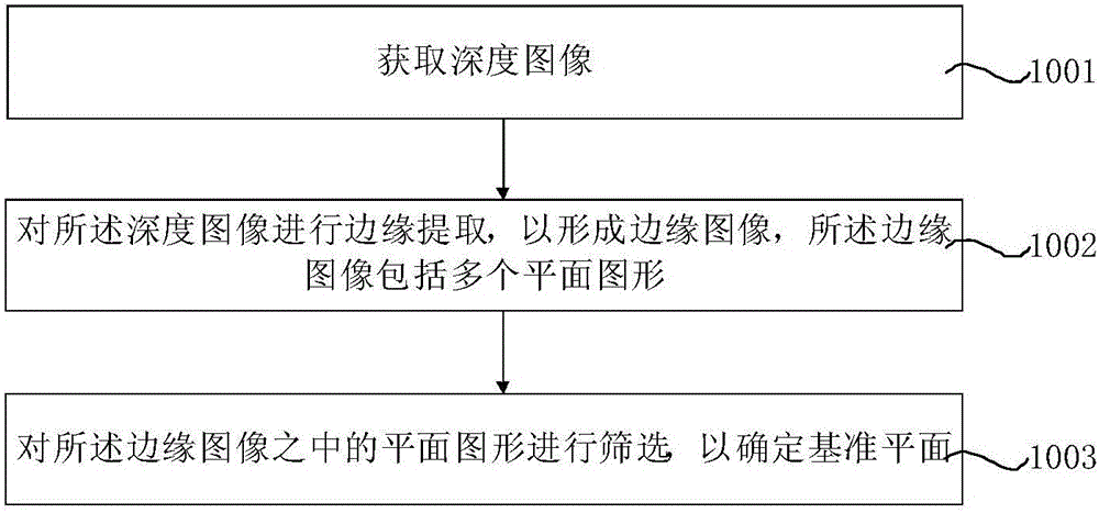
[0073] figure 1 It is a flowchart of a method for determining a reference plane provided by Embodiment 1 of the present invention. Such as figure 1 As shown, the determination method of the reference plane includes:

[0074] Step 1001, acquiring a depth image.

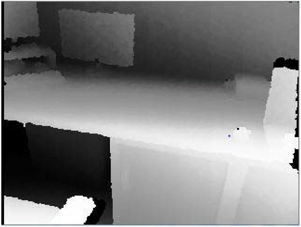
[0075] figure 2 It is the depth image provided by Embodiment 1 of the present invention. Such as figure 2 As shown, in this embodiment, a depth image of an office is acquired through a depth camera. The depth image described in this embodiment is also called a depth image.

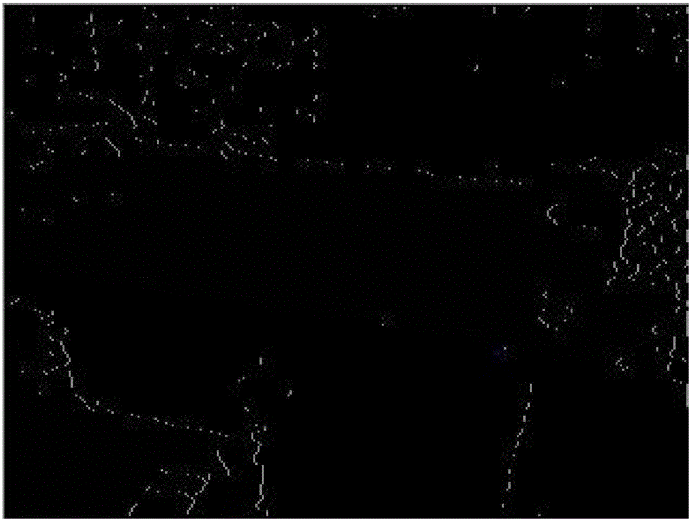
[0076] Step 1002, perform edge extraction on the depth image to form an edge image, and the edge image includes a plurality of plane figures.

[0077] In this embodiment, the step of performing edge extraction on the depth image to form an edge image includes: acquiring the gradient change rate of the depth image according to a preset gradient algorithm; forming a binary image according to the gradient change rate ; Perform edge extractio...

Embodiment 2

[0092] Figure 8 It is a schematic structural diagram of a system for determining a reference plane provided in Embodiment 2 of the present invention. Such as Figure 8 As shown, the system for determining the reference plane includes: a first acquisition unit 101 for acquiring a depth image; a first extraction unit 102 for performing edge extraction on the depth image to form an edge image, and the edge image It includes a plurality of plane figures; the first screening unit 103 is configured to screen the plane figures in the edge image to determine a reference plane.

[0093] see figure 2 , the first acquiring unit 101 acquires a depth image of an office, and the depth image described in this embodiment is also referred to as a depth image. In this embodiment, the first extraction unit 102 includes: a first acquisition module, configured to acquire the gradient change rate of the depth image according to a preset gradient algorithm; a first forming module, configured to...


PUM


Abstract

The invention discloses a reference plane determination method and determination system. The reference plane determination method comprises the steps that a depth image is acquired; edge extraction is performed on the depth image so as to form an edge image, wherein the edge image comprises multiple plane figures; and the plane figures of the edge image are selected through screening so as to determine a reference plane. According to the technical scheme, the reference plane in a real scene can be determined so that a virtual coordinate system can be established based on the reference plane, and finally the objective of mutual fusion of virtual objects and the real scene can be realized. Therefore, the virtual objects and the real scene are mutually fused through the technical scheme so that the experience feeling of real-time matching can be brought to users, and the reference plane determination method and determination system have wearable portability and freedom.

Description

technical field [0001] The present invention relates to the field of display technology, in particular to a method and system for determining a reference plane. Background technique [0002] Augmented Reality (AR for short) is a new technology that "seamlessly" integrates real world information and virtual world information. Specifically, augmented reality technology applies virtual information to the real world, so that the real environment and virtual objects are superimposed on the same picture or the same space in real time, so that they can be perceived by human senses and achieve a sensory experience beyond reality. Therefore, augmented reality technology not only displays the information of the real world, but also displays the information of the virtual world at the same time, and the two kinds of information complement and superimpose each other. [0003] In the field of augmented reality, the optical see-through augmented reality system has the advantages of simpl...

Claims


Application Information

Patent Timeline
IPC IPC(8): G06T7/00
CPCG06T2207/10028G06T7/12G06T7/162G06T2207/20072G06T7/564G06T7/13G06T7/60
Inventor 赵骥伯李英杰
Owner BOE TECH GRP CO LTD
Why Eureka
Try Eureka