Coil component

A technology of coil components and coils, applied in transformer/inductor parts, electrical components, transformer/inductor coils/windings/connections, etc., can solve problems such as deterioration of signal line transmission characteristics, resonance, and signal level deterioration. Achieve the effects of improving impedance, suppressing the deterioration of signal level, and suppressing the deterioration of transmission characteristics

Active Publication Date: 2016-08-03
MURATA MFG CO LTD
View PDF9 Cites 1 Cited by
  • Summary
  • Abstract
  • Description
  • Claims
  • Application Information

AI Technical Summary

Problems solved by technology

[0004] However, if the above-mentioned conventional coil component is mounted in parallel with the signal line of the substrate, there is a problem that resonance occurs in the high-frequency band due to the coil portion wound on the winding core.
As a result, the signal of the signal line is transmitted in the parallel direction, the transmission characteristic of the signal line deteriorates, and the problem of deterioration of the signal level arises.

Method used


Image

  • Coil component
  • Coil component
  • Coil component

Examples


no. 1 Embodiment approach

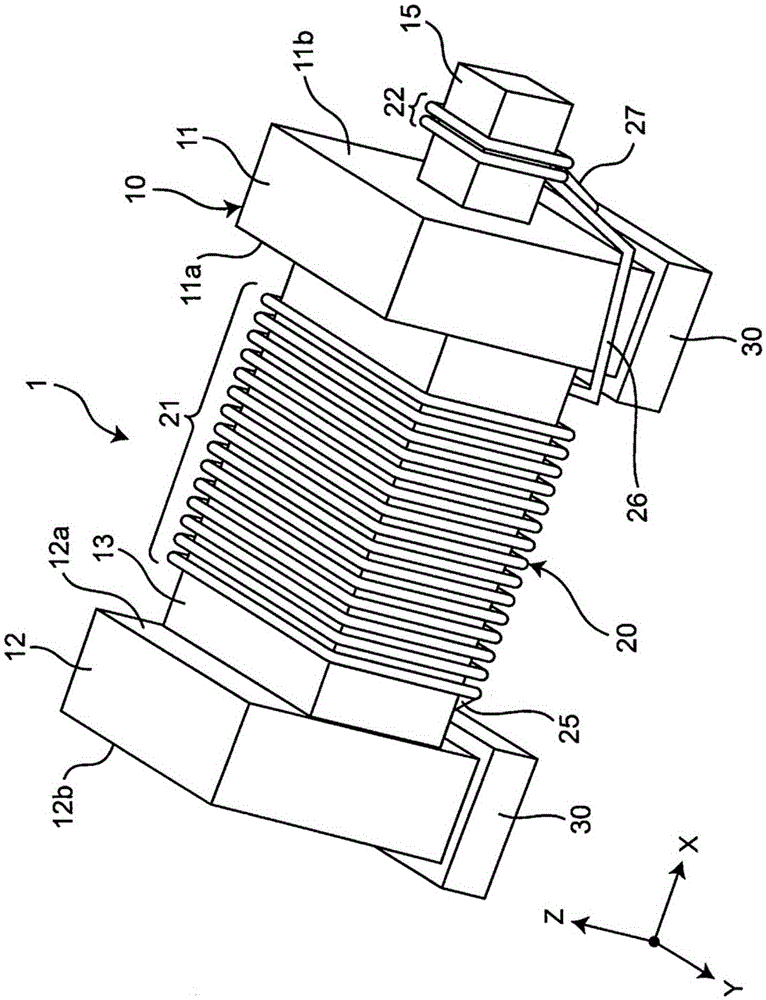
[0048] figure 1 It is a perspective view of the coil component of 1st Embodiment of this invention. Such as figure 1 As shown, the coil component 1 has an iron core 10 , a coil conductor 20 provided on the iron core 10 , and an electrode 30 provided on the iron core 10 .

[0049]The iron core 10 has a winding core portion 13, a first flange portion 11 provided on one end of the winding core portion 13, a second flange portion 12 provided on the other end of the winding core portion 13, and a first flange portion provided on the first flange portion. 11 protrusions 15 . As the material of the iron core 10 , for example, a material having a dielectric constant of 20 or less, such as alumina (non-magnetic material), Ni—Zn-based ferrite (magnetic material, insulator), or resin, is used. The iron core 10 is integrally formed, for example, by press-molding the aforementioned materials with a die.

[0050] Here, let the bottom surface of the iron core 10 be the surface mounted on...

no. 2 Embodiment approach

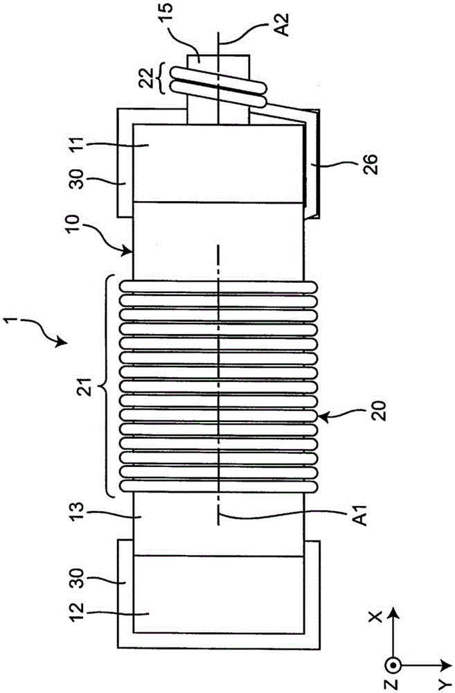
[0074] Figure 5 It is a plan view showing the coil component of the second embodiment of the present invention. The second embodiment is different from the above-mentioned first embodiment in the shape of the second coil portion. Hereinafter, this different configuration will be described. In addition, in 2nd Embodiment, since the same code|symbol as 1st Embodiment represents the same structure as 1st Embodiment, description is abbreviate|omitted.

[0075] Such as Figure 5 As shown, the second coil portion 22A has a meandering shape. The meandering shape is formed in a meandering shape in which straight line portions 22 a and turn-back portions 22 b are alternately connected. The second coil portion 22A is provided on one surface of the protruding portion 15 . 22 A of 2nd coil parts are formed by printing, for example. The material of the second coil portion 22A is, for example, nickel-plated foil or metal foil such as Cu, Al, Au, or Ag.

[0076] The axis A2 of the se...

no. 3 Embodiment approach

[0079] Figure 6It is a plan view showing the coil component of the third embodiment of the present invention. The third embodiment differs from the above-mentioned first embodiment in the position of the second coil portion. This different configuration will be described below. In addition, in 3rd Embodiment, since the same code|symbol as 1st Embodiment is the same structure as 1st Embodiment, description is abbreviate|omitted.

[0080] Such as Figure 6 As shown, the axis A2 of the second coil portion 22 and the axis A1 of the first coil portion 21 are not coaxial but are different axes. In other words, the axis A2 of the second coil portion 22 does not coincide with the axis A1 of the first coil portion 21 on the extension line (not concentric). The axis A2 of the second coil part 22 is parallel to the axis A1 of the first coil part 21 on the extension line thereof.

[0081] Thereby, the second coil part 22 can be brought close to the peripheral edge of the second end ...


PUM


Abstract

A coil component includes a winding core portion; a first flange portion and a second flange portion disposed on both ends of the winding core portion; electrodes disposed on the first flange portion and the second flange portion; a first coil portion and a second coil portion electrically connected between the electrode of the first flange portion and the electrode of the second flange portion and connected to each other in series; and a projection portion disposed on an end surface of the first flange portion on the side opposite to the winding core portion. The first coil portion is disposed on the winding core portion, the second coil portion is disposed on the projection portion, and the first coil portion has an inductance value different from an inductance value of the second coil portion.

Description

technical field [0001] The present invention relates to coil components. Background technique [0002] Conventionally, as a coil component, there is a structure described in Japanese Patent Application Laid-Open No. 5-62022 (Patent Document 1). The coil component has a winding core, flanges provided at both ends of the winding core, electrodes provided on the flanges, and a coil wound around the winding core. [0003] Patent Document 1: Japanese Patent Application Publication No. 5-62022 [0004] However, if the above-mentioned conventional coil component is mounted in parallel with the signal line of the substrate, there is a problem that resonance occurs in a high-frequency band due to the coil portion wound on the winding core portion. As a result, the signal of the signal line is transmitted in the parallel direction, the transmission characteristic of the signal line deteriorates, and there arises a problem that the signal level deteriorates. Contents of the inventi...

Claims


Application Information

Patent Timeline
Patent Type & Authority Applications(China)
IPC IPC(8): H01F17/04H01F27/24H01F27/30
CPCH01F17/045H01F27/24H01F27/306H01F27/006H01F27/2828H01F27/29H01F27/2823
Inventor 盐川登
Owner MURATA MFG CO LTD
Why Eureka
Try Eureka