Differential signal transmission cable and cable with connector

a technology of transmission cable and differential signal, which is applied in the direction of power cables, cables, baseband system details, etc., can solve the problems of skew, and gap caused by shield tape thickness, and achieve the effect of suppressing the deterioration of transmission properties

Active Publication Date: 2015-01-01
HITACHI METALS LTD
View PDF12 Cites 5 Cited by
  • Summary
  • Abstract
  • Description
  • Claims
  • Application Information

AI Technical Summary

Benefits of technology

[0007]It is an object of the present invention to suppress the deterioration in the transmission property of the differential signal transmission cable due to the gap caused between the insulator and the shield tape.

Problems solved by technology

Therefore, a gap due to a thickness of the shield tape is caused between the insulator and the shield tape.
This gap causes deterioration in transmission property such as increase in skew and increase in a conversion volume of the differential phase to / from the common phase (differential / common-phase conversion).

Method used


Image

  • Differential signal transmission cable and cable with connector
  • Differential signal transmission cable and cable with connector
  • Differential signal transmission cable and cable with connector

Examples


Embodiment Construction

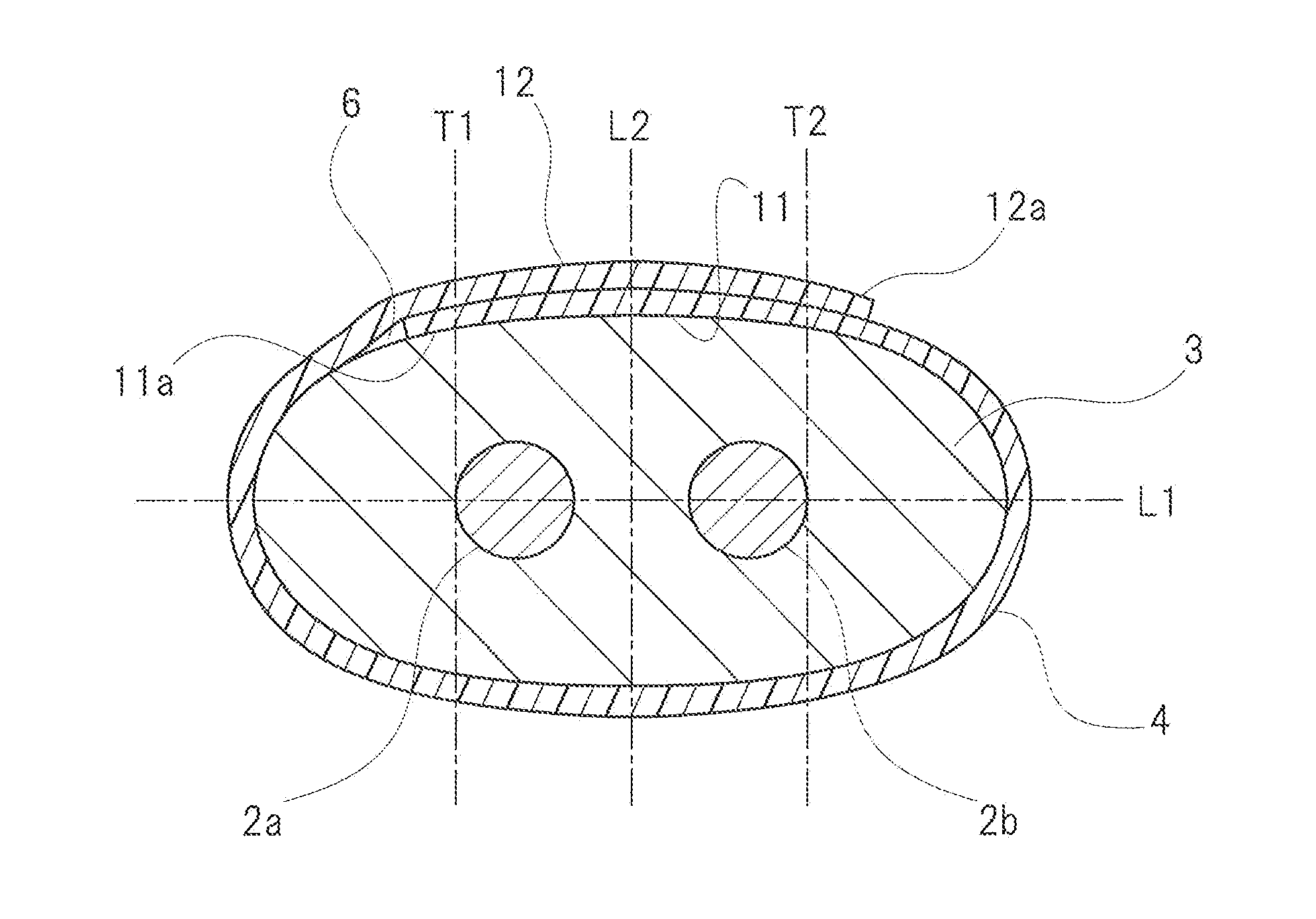
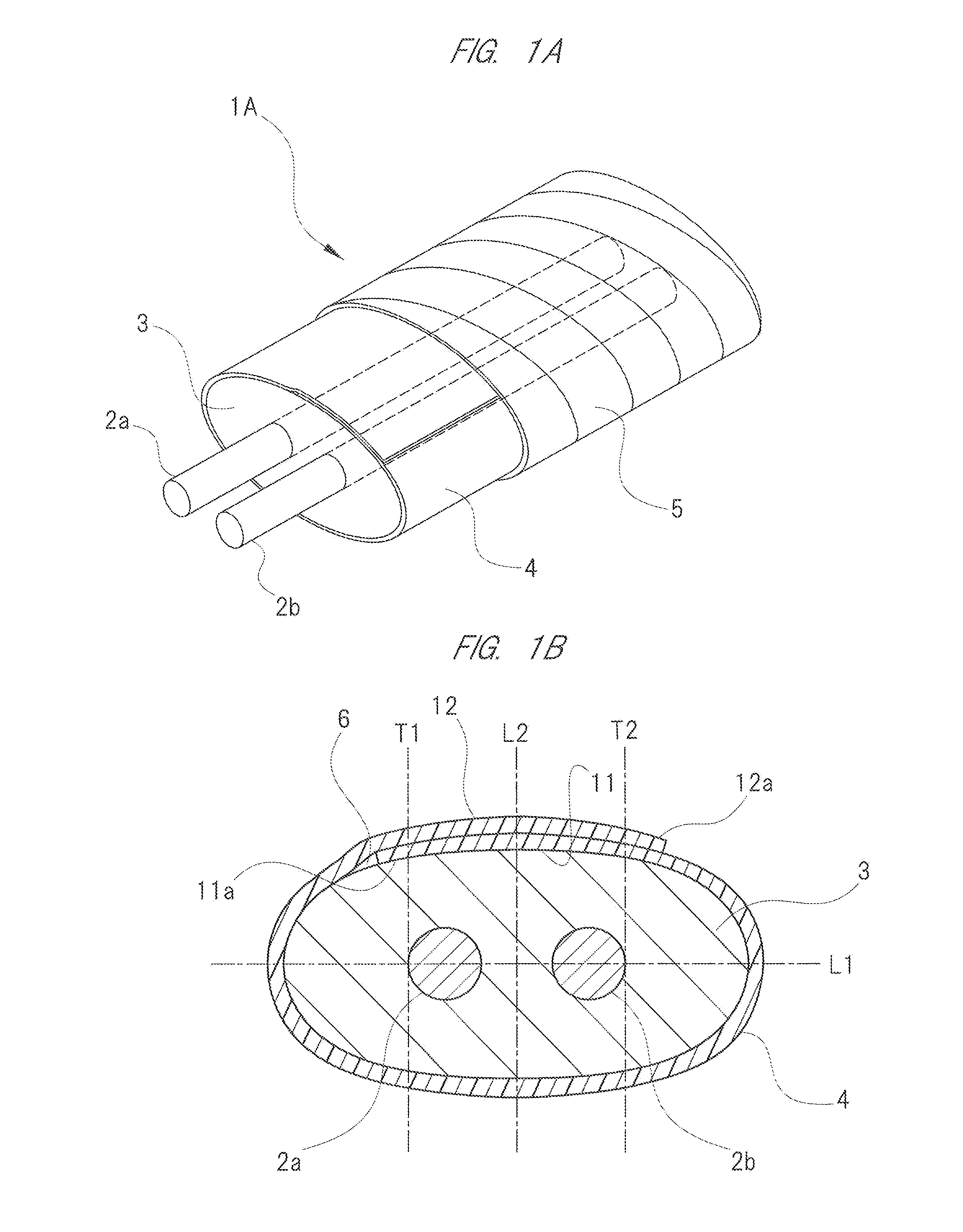
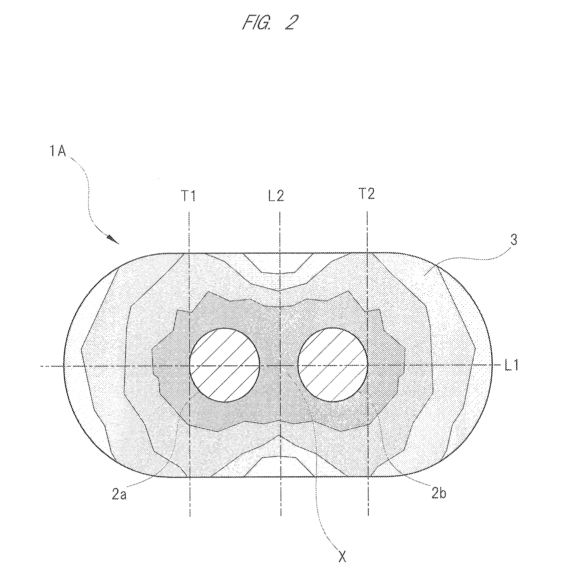
[0025]Hereinafter, exemplary embodiments of the present invention will be explained in detail with reference to the drawings. As illustrated in FIG. 1A, a differential signal transmission cable 1A according to the present embodiment includes a first signal conductor 2a and a second signal conductor 2b. That is, the differential signal transmission cable 1A includes a pair of signal conductors 2a and 2b. A plus-side (positive) signal is transmitted to either one of the pair of signal conductors 2a and 2b, and a minus-side (negative) signal is transmitted to the other of the pair of signal conductors 2a and 2b. Each of the signal conductors 2a and 2b is made of an annealed copper wire (silver plated copper wire) whose surface is subjected to silver plating treatment and whose cross-sectional surface is circular. The pair of signal conductors 2a and 2b are covered together with a common insulator 3.

[0026]The insulator 3 is made of, for example, foamed polyethylene (Expanded Poly-Ethyle...


PUM

PropertyMeasurementUnit
melting temperatureaaaaaaaaaa
transmission rateaaaaaaaaaa
phasesaaaaaaaaaa

Abstract

A differential signal transmission cable includes: two signal conductors; an insulator for covering these signal conductors; and a shield tape wound around the insulator in longitudinal wrapping. In the differential signal transmission cable, both ends of the shield tape in a direction of the winding around the insulator have a first overlapping region and a second overlapping region which overlap each other, and the first overlapping region of the shield tape is covered with the second overlapping region. In a tangent line of two tangent lines of a first signal conductor which is orthogonal to a line passing through centers of the signal conductors, when the tangent line positioned at radially outside of the first signal conductor is set to be a first tangent line, an end of the first overlapping region is positioned at outside of the first tangent line.

Description

CROSS-REFERENCE TO RELATED APPLICATION[0001]The present application claims priority from Japanese Patent Application No. 2013-136442 filed on Jun. 28, 2013, the content of which is hereby incorporated by reference into this application.TECHNICAL FIELD OF THE INVENTION[0002]The present invention relates to a differential signal transmission cable and a cable with a connector for transmitting two or more signals whose phases are different from each other.BACKGROUND OF THE INVENTION[0003]The differential interface standard (for example, LVDS (Low Voltage Differential Signaling)) is adopted to devices such as a server, a router, and a storage in which high-speed digital signals of several Gbit / s or higher are handled, and differential signals are transmitted by using a differential signal transmission cable between devices or between circuit boards in the device. The differential signals have such an advantage as high noise immunity to exogenous noises while achieving low voltage of a s...

Claims


Application Information

Patent Timeline
Patent Type & Authority Applications(United States)
IPC IPC(8): H01B11/00H04L25/02
CPCH01B11/002H04L25/0272H01B11/1016
Inventor WATANABE, HARUYUKIOIKAWA, MINORU
Owner HITACHI METALS LTD
Why Eureka
Try Eureka