Optical transmission system in which gains in gain bands are remotely controlled by transmitting tone signals having variable characteristics

a technology of optical transmission system and tone signal, which is applied in the direction of transmission monitoring, electromagnetic repeaters, multiplex communication, etc., can solve problems such as transmission characteristics deterioration, and achieve the effect of suppressing transmission characteristics and high-quality optical transmission

Active Publication Date: 2006-04-18
FUJITSU LTD
View PDF18 Cites 4 Cited by
  • Summary
  • Abstract
  • Description
  • Claims
  • Application Information

AI Technical Summary

Benefits of technology

[0008]An object of the present invention is to provide an optical transmission system in which deterior...

Problems solved by technology

Therefore, gains in the respective gain bands dif...

Method used


Image

  • Optical transmission system in which gains in gain bands are remotely controlled by transmitting tone signals having variable characteristics
  • Optical transmission system in which gains in gain bands are remotely controlled by transmitting tone signals having variable characteristics
  • Optical transmission system in which gains in gain bands are remotely controlled by transmitting tone signals having variable characteristics

Examples


first embodiment

(3) Optical Repeater in First Embodiment

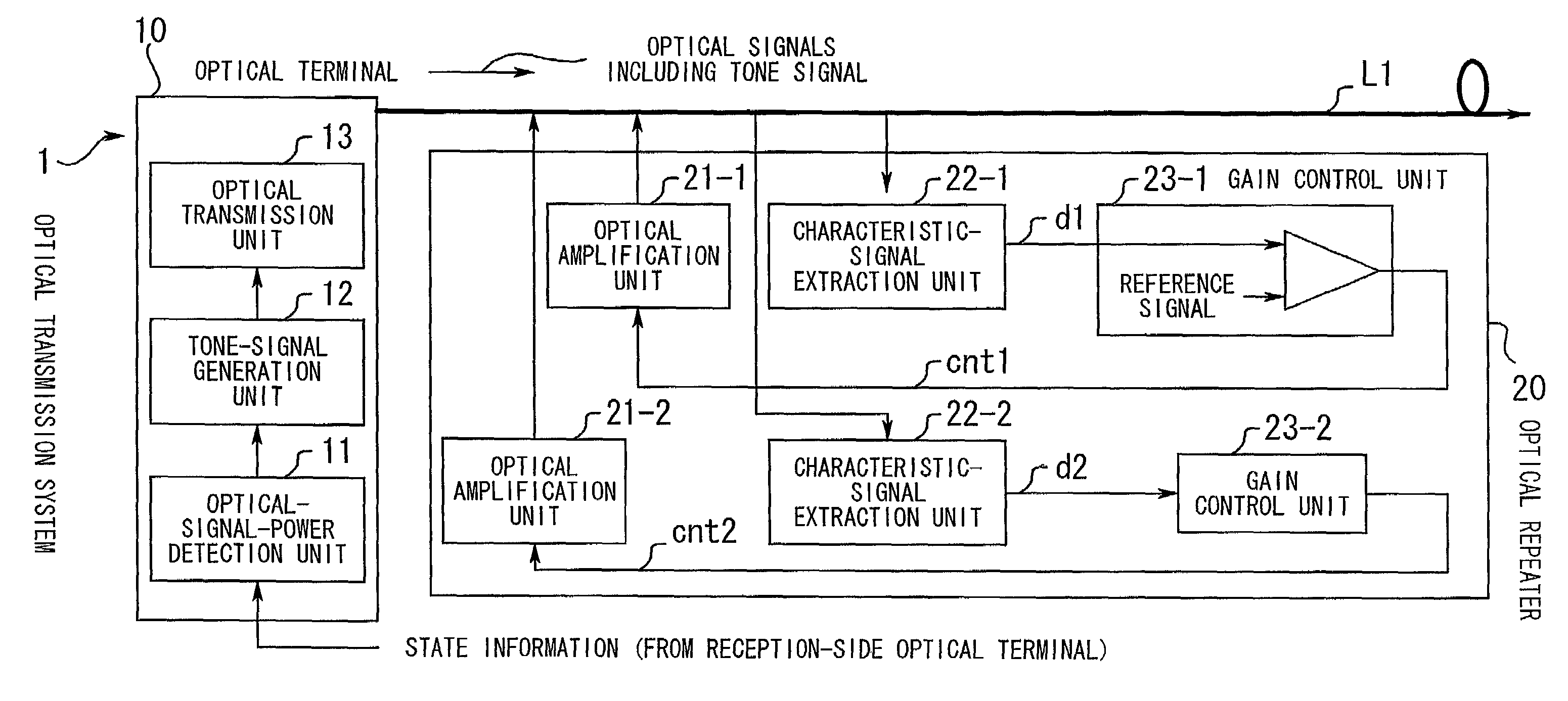
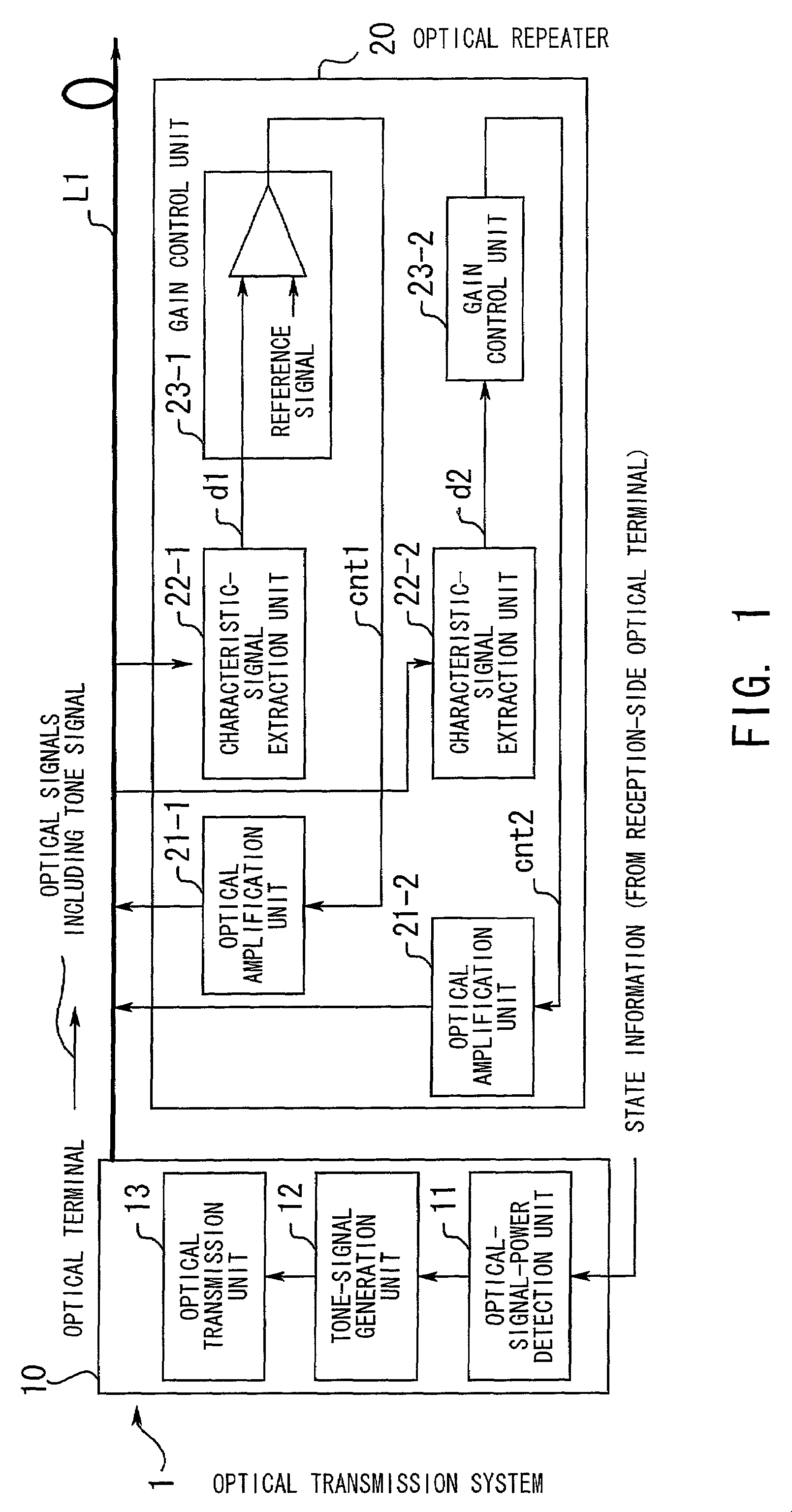
[0078]FIG. 7 is a diagram illustrating an example of the optical repeater 20 which is used in the optical transmission system of FIG. 1 in the first embodiment of the present invention. In FIG. 7, only the elements relevant to the present invention are illustrated. The optical repeater of FIG. 7 comprises optical couplers C1 to C3, a photodiode 2, filters F1 and F2, smoothing units 22a-1 and 22a-2, gain control units 23-1 and 23-2, and excitation light sources LD1 and LD2.

[0079]The excitation light sources LD1 and LD2 are provided for the excitation light sources in the Raman gain bands G1 and G2, respectively.

[0080]The operation for controlling Raman amplification in the Raman gain band G1 is performed as follows.

[0081]First, optical signals transmitted from the optical terminal 10 through the upstream transmission line L1 are branched through the optical coupler C2 from the upstream transmission line L1, and received by the photodiode 2.

[008...

second embodiment

(4) Optical Repeater in Second Embodiment

[0112]FIG. 14 is a diagram illustrating an example of the optical repeater in the second embodiment of the present invention. In the second embodiment, the optical repeater 20a of FIG. 14 is used instead of the optical repeater 20 of FIG. 7. In FIG. 14, elements having the same functions as the elements in the optical repeater of FIG. 7 bear the same reference numerals as FIG. 7, respectively.

[0113]The optical repeater 20a of FIG. 14 is arranged to concurrently realize Raman excitation in both of two upstream transmission lines L1a and L1b.

[0114]The optical repeater of FIG. 14 comprises, on the side of the upstream transmission line L1a, optical couplers C1 and C2, a photodiode 2a, filters F1a and F2a, and smoothing units 22a-1 and 22a-2. In addition, the optical repeater 20a of FIG. 14 comprises, on the side of the upstream transmission line L1b, optical couplers C4 and C5, a photodiode 2b, filters F1b and F2b, and smoothing units 22b-1 and...

third embodiment

(5) Optical Repeater in Third Embodiment

[0124]FIG. 15 is a diagram illustrating an example of an optical repeater in the third embodiment of the present invention. In the third embodiment, the optical repeater 20b of FIG. 15 is used instead of the optical repeater 20 of FIG. 7. In FIG. 15, elements having the same functions as the elements in the optical repeater of FIG. 7 bear the same reference numerals as FIG. 7, respectively.

[0125]The optical repeater 20b of FIG. 15 is arranged to realize Raman amplification in more than two Raman gain bands.

[0126]The optical repeater 20b of FIG. 15 comprises optical couplers C1 and C2, a photodiode 2, n filters F1 to Fn, n smoothing units 22a-1 to 22a-n, n gain control units 23-1 to 23-n, n excitation light sources LD1 to LDn, and an optical multiplexer 25, where n is an integer greater than two. The filter F1, the smoothing unit 22a-i, the gain control unit 23-i, and the excitation light source LDi are provided corresponding to a Raman gain ba...


PUM


Abstract

In an optical transmission system, an optical terminal transmits a plurality of tone signals corresponding to a plurality of gain bands, where the frequencies of the plurality of tone signals are different from each other, and each of the plurality of tone signals has a characteristic which is varied according to detected power of optical signals in the corresponding gain band. Each optical repeater receives the plurality of tone signals, extracts the characteristics of the plurality of tone signals, and compares a signal representing each characteristic with a reference signal. The optical repeater controls the gains of optical amplification in the plurality of gain bands based on the comparison result so as to equalize the gains in the plurality of gain bands.

Description

BACKGROUND OF THE INVENTION[0001]1) Field of the Invention[0002]The present invention relates to an optical transmission system in which optical amplification is realized in a plurality of gain bands. The present invention also relates to an optical terminal used in the above optical transmission system. The present invention further relates to an optical repeater used in the above optical transmission system.[0003]2) Description of the Related Art[0004]Recently, optical fiber amplifiers which utilize a nonlinear optical phenomenon occurring in optical fibers and being called Raman amplification are receiving attention in the field of optical communications. In the Raman amplification, a physical phenomenon in which vibrations of materials inelastically scatter incident light so as to produce Raman scattered light having a wavelength which is different from the wavelength of the incident light is utilized, and strong excitation light is injected into an optical-fiber transmission li...

Claims


Application Information

Patent Timeline
IPC IPC(8): H04B10/08H04B10/00H04B10/02H04J14/02H01S3/10H01S3/30H04B10/07H04B10/2507H04B10/29H04B10/293H04B10/294H04B10/54H04B10/564H04B10/572H04B10/58
CPCH04B10/0777H04B10/2942H04B10/2916H04B2210/075
Inventor HARASAWA, SHIN-ICHIROU
Owner FUJITSU LTD
Why Eureka
Try Eureka