Radio-frequency front-end circuit

a front-end circuit and radio frequency technology, applied in the direction of transmission, electrical equipment, etc., can solve the problems of difficult control of the characteristics of multiplexers, increase in the loss of insertion due to each switched terminal, etc., to suppress the loss of radio frequency signals transferred through the single filter, excellent transfer characteristics, and suppress the effect of deterioration of the transfer characteristi

Active Publication Date: 2021-01-07
MURATA MFG CO LTD
View PDF0 Cites 1 Cited by
  • Summary
  • Abstract
  • Description
  • Claims
  • Application Information

AI Technical Summary

Benefits of technology

[0024]With this configuration, the loss of radio frequency signals transferred through the single filter is suppressed.
[0025]The present disclosure can suppress deterioration of the transfer characteristic and achieve an excellent transfer characteristic with the configuration including radio-frequency switches and a plurality of filters configured to be switched by the radio-frequency switches.

Problems solved by technology

Then, in the switch element, as the number of terminals to be switched increases, the insertion loss due to each of the switched terminals increases.
Moreover, it is difficult to control the characteristics of a multiplexer, such as a duplexer, in which a plurality of filters are bundled together.

Method used


Image

  • Radio-frequency front-end circuit
  • Radio-frequency front-end circuit
  • Radio-frequency front-end circuit

Examples


first embodiment

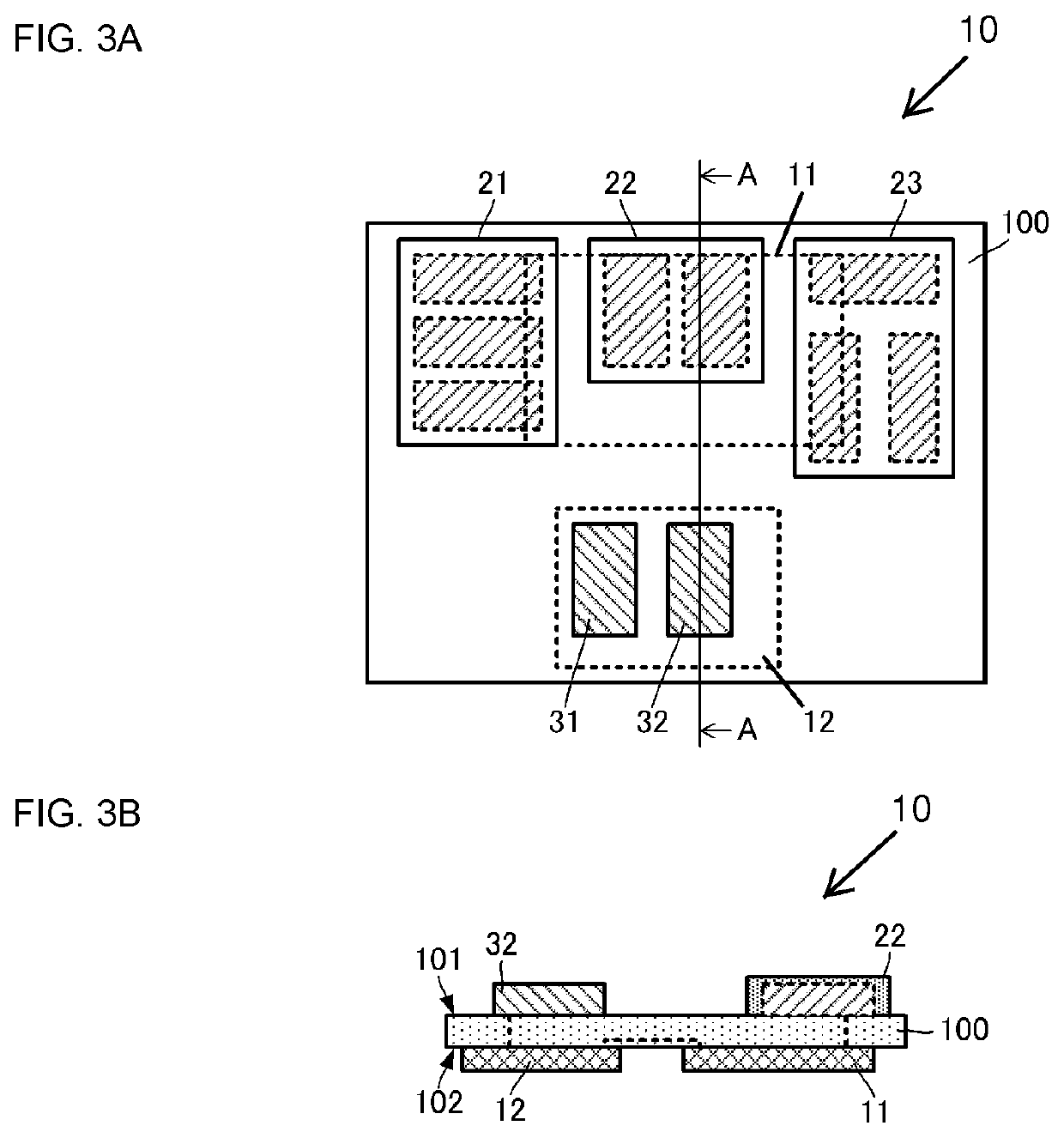
[0089]The radio-frequency front-end circuit 10 having the circuit configuration described above can be implemented by using, for example, the structures illustrated in FIGS. 3A and 3B. FIG. 3A is a plan view schematically illustrating a structure of the radio-frequency front-end circuit 10 according to the present disclosure and FIG. 3B is a sectional view taken along line A-A in FIG. 3A.

[0090]As illustrated in FIGS. 3A and 3B, the radio-frequency front-end circuit 10 includes a base 100. The base 100 is formed as a flat plate and has major surfaces 101 and 102 opposite to each other. Conductor patterns that are mainly made of an insulating material and that constitute the circuit configuration of the radio-frequency front-end circuit 10 are formed at the base 100.

[0091]The filters 21, 22, 23, 31, and 32 are formed at the major surface 101 of the base 100.

[0092]The radio-frequency switches 11 and 12 are formed at the major surface 102 of the base 100.

[0093]The filters 21, 22, and 23...

second embodiment

[0100]The radio-frequency front-end circuit 10A differs from the radio-frequency front-end circuit 10 in the configuration in which a filter 23A is formed as a multiplexer composed of two single filters, the configuration in which the filter 33 is added to the configuration, and the configuration of a radio-frequency switch 12A. The other configurations of the radio-frequency front-end circuit 10A are the same as those of the radio-frequency front-end circuit 10, and the description thereof is not repeated.

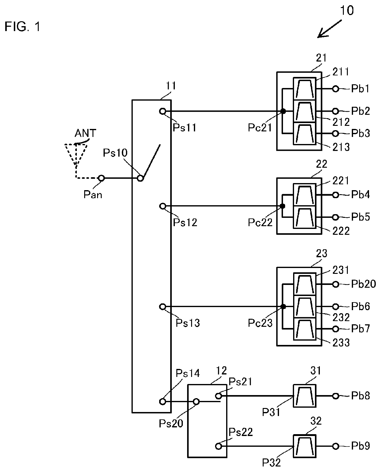
[0101]The radio-frequency switch 12A is a single-pole triple-throw (SP3T) switch. The radio-frequency switch 12A includes one antenna-side terminal Ps20 and a plurality of filter-side terminals Ps21, Ps22, and Ps23. The radio-frequency switch 12A selectively connects any of the terminals Ps21, Ps22, and Ps23 to the terminal Ps20.

[0102]The filter 23A includes the filters 231 and 232. One terminal of the filter 231 and one terminal of the filter 232 are coupled to each other and th...

third embodiment

[0107]The radio-frequency front-end circuit 10B differs from the radio-frequency front-end circuit 10A in the configuration in which a filter 21B is formed as a multiplexer composed of two single filters, the configuration in which a filter 34 is added to the configuration, and the configuration of radio-frequency switches 11B and 12B. The other configurations of the radio-frequency front-end circuit 10B are the same as those of the radio-frequency front-end circuit 10A, and the description thereof is not repeated.

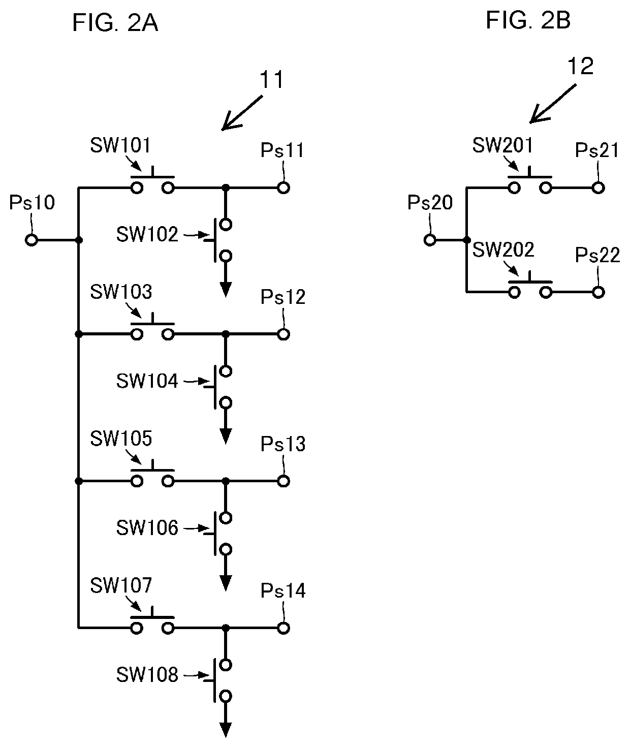
[0108]The radio-frequency switch 11B is a single-pole five-throw (SPST) switch. The radio-frequency switch 11B includes one antenna-side terminal Ps10 and a plurality of filter-side terminals Ps11, Ps12, Ps13, Ps14, and Ps15. The radio-frequency switch 11B selectively connects any of the terminals Ps11, Ps12, Ps13, Ps14, and Ps15 to the terminal Ps10. At this time, the radio-frequency switch 11B causes one of the terminals Ps11, Ps12, Ps13, Ps14, and Ps15 to be connected ...


PUM


Abstract

A radio-frequency front-end circuit includes first and second radio-frequency switches and filters. The first radio-frequency switch includes a first antenna-side terminal and a plurality of first filter-side terminals selectively coupled to the first antenna-side terminal. The second radio-frequency switch includes a second antenna-side terminal and a plurality of second filter-side terminals selectively coupled to the second antenna-side terminal. Some of the filters are multiplexer filters and each includes a common terminal. The common terminals of the filters are coupled individually to some of the first filter-side terminals of the first radio-frequency switch. The second antenna-side terminal of the second radio-frequency switch is coupled to the remaining one of the first filter-side terminals of the first radio-frequency switch.

Description

[0001]This is a continuation of International Application No. PCT / JP2019 / 010270 filed on Mar. 13, 2019 which claims priority from Japanese Patent Application No. 2018-064042 filed on Mar. 29, 2018. The contents of these applications are incorporated herein by reference in their entireties.BACKGROUND[0002]The present disclosure relates to a radio-frequency front-end circuit for communicating radio frequency signals in a plurality of communication bands.[0003]In recent years, communication terminals, such as mobile communication devices are required to be downsized and also required to support a plurality of communication bands by a single communication terminal.[0004]To implement such communication terminals, for example, a radio-frequency module described in Japanese Unexamined Patent Application Publication No. 2014-050098 (Patent Document 1) includes a switch element and multiple kinds of filters.[0005]The switch element includes an antenna-side connection terminal coupled to an a...

Claims


Application Information

Patent Timeline
Patent Type & Authority Applications(United States)
IPC IPC(8): H04B1/00H04B1/04H04B1/16
CPCH04B1/006H04B1/1607H04B1/04H04B1/0078H04B1/0057H04B1/52
Inventor TAKEUCHI, MORIO
Owner MURATA MFG CO LTD
Why Eureka
Try Eureka