Antenna system, terminal and control method for radio frequency signals

An antenna system and radio frequency signal technology, applied to antennas, devices that enable antennas to work in different bands at the same time, antenna supports/installation devices, etc., can solve problems such as increased absorption loss, signal fading, and antenna resonance frequency offset. Achieve the effect of increasing RF energy and reducing fading

Active Publication Date: 2016-08-03
VIVO MOBILE COMM CO LTD
View PDF3 Cites 43 Cited by
  • Summary
  • Abstract
  • Description
  • Claims
  • Application Information

AI Technical Summary

Problems solved by technology

[0005] The purpose of the embodiments of the present invention is to provide a control method for an antenna system, a terminal, and a radio frequency signal, so as to solve the problem that when a hand or a head is added to a terminal, the resonant frequency of the antenna will be greatly shifted, the absorption loss will be increased, and the signal will rapidly fade The problem

Method used


Image

  • Antenna system, terminal and control method for radio frequency signals
  • Antenna system, terminal and control method for radio frequency signals
  • Antenna system, terminal and control method for radio frequency signals

Examples


no. 1 example

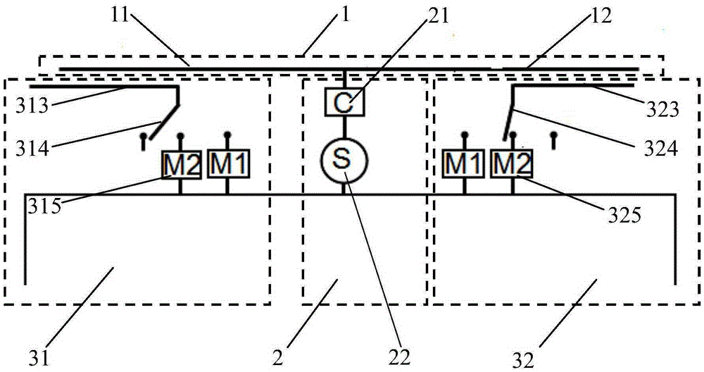
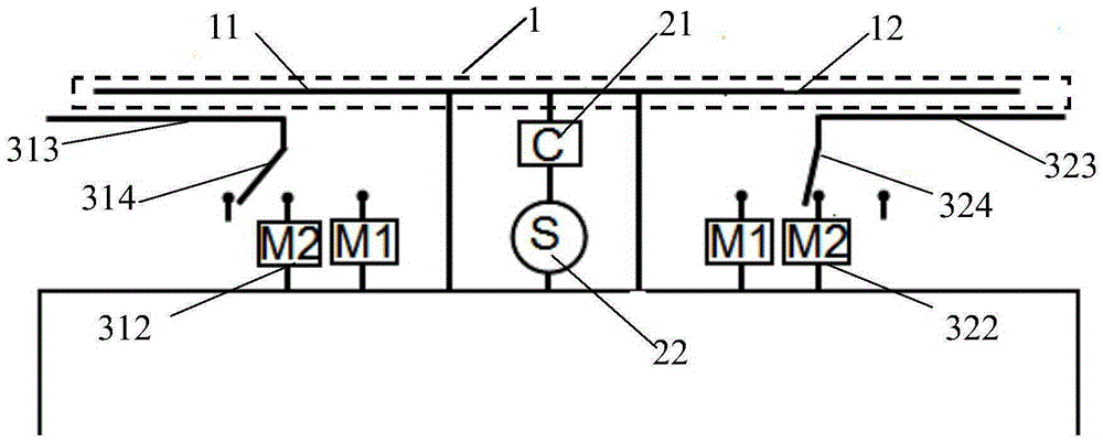
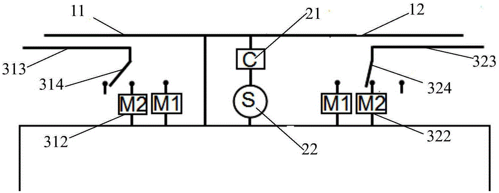
[0035] Such as figure 1 As shown, the antenna system includes: an antenna radiator 1, including a first antenna branch 11 and a second antenna branch 12 connected to the first antenna branch 11, a signal generating circuit 2 connected to the antenna radiator 1, and the A first coupling circuit 31 coupled to the first antenna branch 11 and a second coupling circuit 32 coupled to the second antenna branch 12;

[0036] The antenna system is in the first connection state, the first connection state is that the first coupling circuit 31 is disconnected from the first antenna branch 11, the first antenna branch 11 transmits a first radio frequency signal with a first frequency, and the first radio frequency signal is transmitted by the first antenna branch 11. The second coupling circuit 32 is coupled and connected to the second antenna branch 12, the second antenna branch 12 transmits a second radio frequency signal of a first frequency, and the radio frequency energy of the first...

no. 2 example

[0072] Such as Figure 14 As shown, the difference between the antenna system and the first embodiment is that the antenna system further includes: a sensor 71 for sensing the object to be detected and a first controller 72;

[0073] Wherein, the output end of the sensor 71 is connected with the input end of the first controller 72, and the output end of the first controller 72 is respectively connected with the first switch and the second switch;

[0074] The sensor 71 senses the object to be detected, and outputs an induction signal of the object to be detected to the first controller 72, and the first controller 72 compares the induction signal with the preset object to be detected in the preset switching, Outputting a first switching signal corresponding to the object to be detected in the preset switching, controlling one switch to be turned off and the other switch to be turned on according to the first switching signal, and controlling the antenna through the first swit...

no. 3 example

[0083] Such as Figure 15 As shown, the difference between the antenna system and the first embodiment is that there is a feed point between the feed device 21 and the feed source 22, and the antenna system also includes: a detection control circuit 5, the input of the detection control circuit 5 The terminal is connected to the feed point, and the output terminals of the detection control circuit 5 are respectively connected to the first switch and the second switch.

[0084] Above-mentioned detection control circuit 5 is used for detecting the signal to be detected of input and output switching signal, and this switching signal is by detection control circuit 5 (such as Figure 14 to Figure 17 ) generation, specifically coupled with the first antenna branch 11, or coupled with the second antenna branch 12, are all related to the switching signal; the above-mentioned detection control circuit 5 is aimed at the detection of the radio frequency energy change, the detection of t...


PUM


Abstract

The invention provides an antenna system, a terminal and a control method for radio frequency signals. The antenna system comprises an antenna radiator, a signal generating circuit, a first coupling circuit and a second coupling circuit. The antenna radiator comprises a first antenna branch and a second antenna branch. The antenna system is in such a first connection state that: the first coupling circuit and the first antenna branch are in coupling disconnection with each other; the first antenna branch sends out a first radio frequency signal at a first frequency; the second coupling circuit and the second antenna branch are in coupling connection with each other; the second antenna branch sends out a second radio frequency signal at the first frequency; and the radio frequency energy of the first radio frequency signal is smaller than the radio frequency energy of the second radio frequency signal. Or, the antenna system is in such a second connection state that: the first coupling circuit and the first antenna branch are in coupling connection with each other; the first antenna branch sends out the first radio frequency signal; the second coupling circuit and the second antenna branch are in coupling disconnection with each other; the second antenna branch sends out the second radio frequency signal; and the radio frequency energy of the first radio frequency signal is larger than the radio frequency energy of the second radio frequency signal. The antenna system is controlled to be in the first connection state or the second connection state.

Description

technical field [0001] The invention relates to antenna technology, in particular to an antenna system, a terminal and a control method for radio frequency signals. Background technique [0002] At present, major operators and terminal manufacturers attach great importance to the antenna performance of mobile terminals under the head-hand model, and put forward specific requirements for the performance of the left and right head-hand models. However, how to solve the problem of large head-hand model absorption and large left-right difference is still a difficult issue in the industry, especially for metal-looking mobile terminals. [0003] In recent years, mobile terminals with a metal appearance have become popular, and antennas generally need to use metal components, which significantly increases the impact of human heads or hands, especially human hands. Adding hands will not only greatly shift the resonant frequency of the antenna, resulting in serious mismatch, but als...

Claims


Application Information

Patent Timeline
Patent Type & Authority Applications(China)
IPC IPC(8): H01Q5/10H01Q5/321H01Q5/371H01Q1/22
Inventor 李日辉
Owner VIVO MOBILE COMM CO LTD
Why Eureka
Try Eureka