Method and device for decoding data streams
A decoding method and data stream technology, applied in the direction of digital video signal modification, electrical components, image communication, etc., can solve the problem of low decoding speed, and achieve the effect of improving decoding speed, simplifying circuit structure, and saving FPGA resources.
- Summary
- Abstract
- Description
- Claims
- Application Information
AI Technical Summary
Problems solved by technology
Method used
Image


Examples
Embodiment Construction
[0025] Hereinafter, the present invention will be described in detail with reference to the drawings and examples. It should be noted that, in the case of no conflict, the embodiments in the present application and the features in the embodiments can be combined with each other.
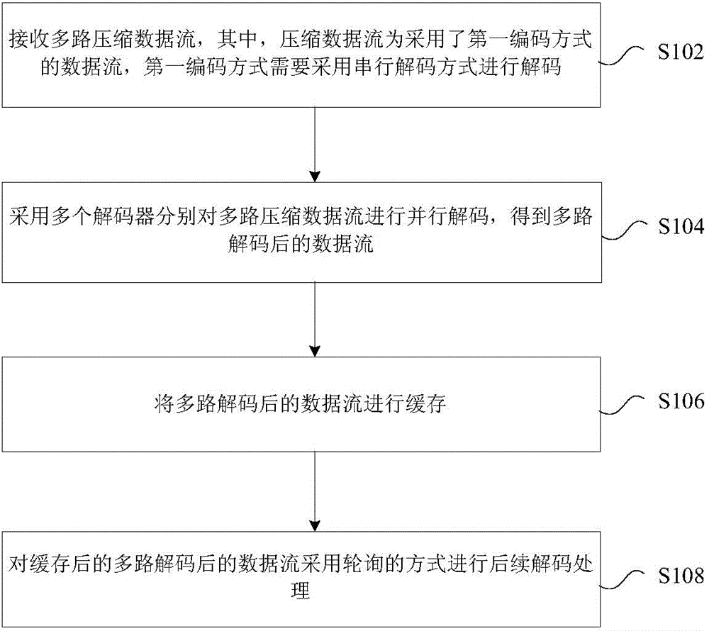
[0026] In this embodiment, a decoding method of a data stream is provided, figure 2 is a flowchart of a decoding method of a data stream according to an embodiment of the present invention, such as figure 2 As shown, the process includes the following steps:
[0027] Step S102, receiving multiple compressed data streams, wherein the compressed data stream is a data stream using a first coding method, and the first coding method needs to be decoded by using a serial decoding method;
[0028] Step S104, using a plurality of decoders to respectively decode multiple compressed data streams in parallel to obtain multiple decoded data streams;
[0029] Step S106, buffering the multi-channel decoded da...
PUM
 Abstract
Description
Claims
Application Information