


Quick Research
Generate reliable direction feasibility study reports for your R&D in just a few steps.

Technical Q&A
Discover and master advanced knowledge NOW. Basics, ideas, possibilities, all at once.

Find Solutions
As an expert in R&D theories, this can generate solutions to your technical problems instantly.

Evaluate Feasibility
Analyze your overall solution with one click, know your potential R&D risks in advance.

Monitor Landscape
Get weekly tech updates, stay abreast of the latest tech innovations and key insights.
Device for manufacturing uneven-thickness film, and method for manufacturing uneven-thickness film
一种制造装置、膜厚的技术,应用在合成树脂制的膜厚不均膜领域,能够解决长加压、过大压力、制造成本増加等问题
- Summary
- Abstract
- Description
- Claims
- Application Information
AI Technical Summary
Problems solved by technology
Method used
Image

Examples
no. 1 approach
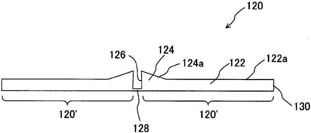
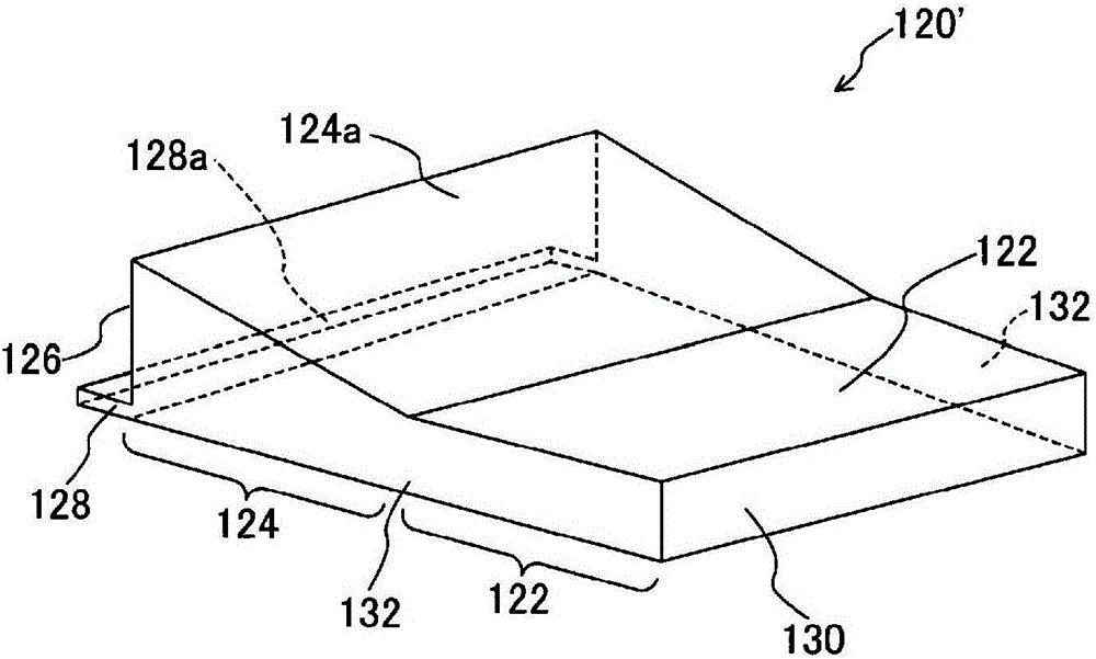
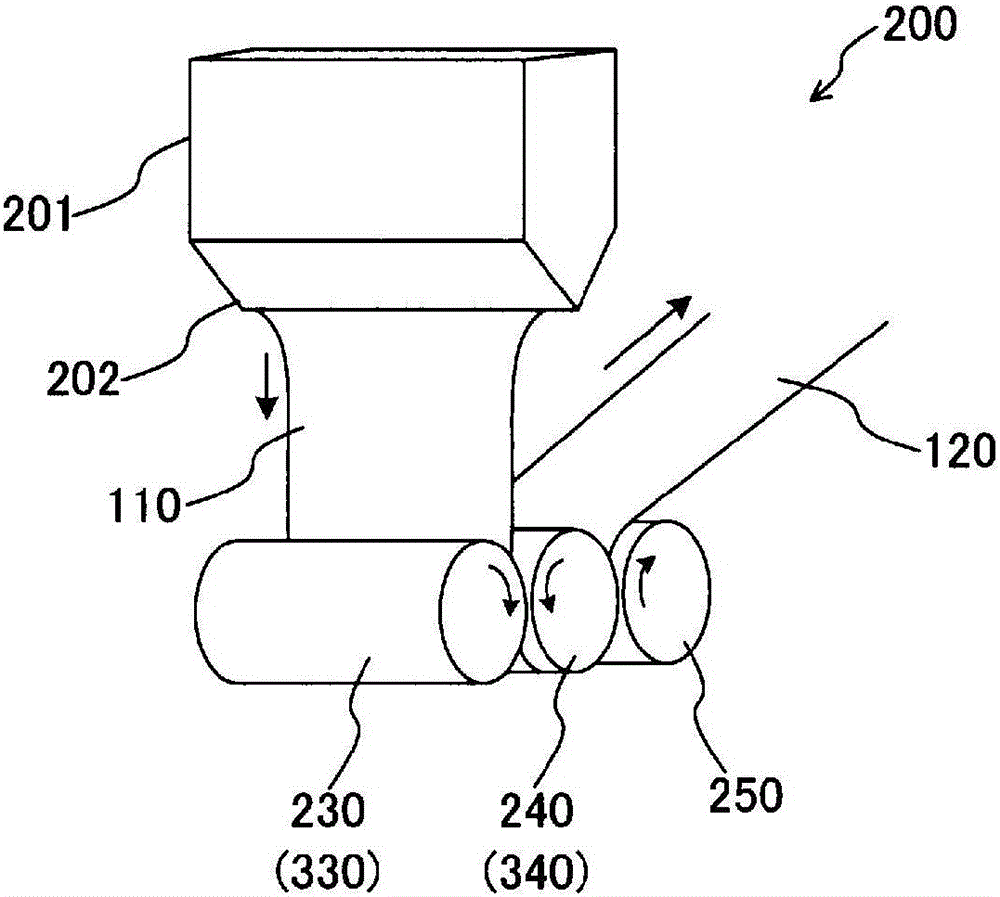
[0031] figure 1 It is a sectional view in a direction perpendicular to the extrusion (longitudinal) direction of a molded body of a film with uneven film thickness extrusion-molded by the manufacturing apparatus and method of the first embodiment. The shaped body 120 is composed of two sub-shaped bodies 120'. The sub-formed body 120' has a flat portion 122 having a uniform film thickness, a non-uniform film thickness portion 124 having a variable film thickness, and a connection portion 128 having a thinner film thickness than the flat portion 122. Preferably, the connecting portion 128 can be formed to have substantially the same film thickness between the disk-shaped portion 232 of the first roller 230 described later and the cylindrical portion of the second roller 240 . The upper surface of the molded body 120' is formed to stand up on the side of the uneven film thickness portion 124, and the lower surface of the molded body 120' is flat. The wall thickness (film thickn...
no. 2 approach
[0040] Figure 5 It is a cross-sectional view in a direction perpendicular to the extrusion direction of a molded body of a film with uneven film thickness that is extrusion-molded by the manufacturing apparatus and method of the second embodiment. The shaped body 220 is composed of two sub-shaped bodies 220'. The sub-formed body 220' has a flat portion 222 having a uniform film thickness, a non-uniform film thickness portion 224 having a variable film thickness, and a connection portion 228 having a thinner film thickness than the flat portion 222. The upper surface of the molded body 220' is formed to stand up from the uneven film thickness portion 224, and the lower surface of the molded body 220' is flat. The wall thickness (film thickness) of the uneven film thickness portion 224 decreases from the first side portion 226 on the connection portion 228 side to the second side portion 230 on the flat portion 232 side. The side portions 126 of the two uneven film thickness ...
PUM
 Abstract
Description
Claims
Application Information
 - R&D Engineer
- R&D Manager
- IP Professional
- Industry Leading Data Capabilities
- Powerful AI technology
- Patent DNA Extraction
Browse by: Latest US Patents, China's latest patents, Technical Efficacy Thesaurus, Application Domain, Technology Topic, Popular Technical Reports.
© 2024 PatSnap. All rights reserved.Legal|Privacy policy|Modern Slavery Act Transparency Statement|Sitemap|About US| Contact US: help@patsnap.com