Caliper brake for elevator installations

A technology for caliper brakes and elevators, used in transportation and packaging, elevators, etc., which can solve problems such as fatigue fracture, vibration, and brake caliper trembling

Active Publication Date: 2016-08-03
INVENTIO AG
View PDF8 Cites 6 Cited by
  • Summary
  • Abstract
  • Description
  • Claims
  • Application Information

AI Technical Summary

Problems solved by technology

In the worst case, the calipers may even vibrate or vibrate
This can produce fatigue fractures in the spring accumulator or in the individual windings of the spring

Method used


Image

  • Caliper brake for elevator installations
  • Caliper brake for elevator installations
  • Caliper brake for elevator installations

Examples


Embodiment Construction

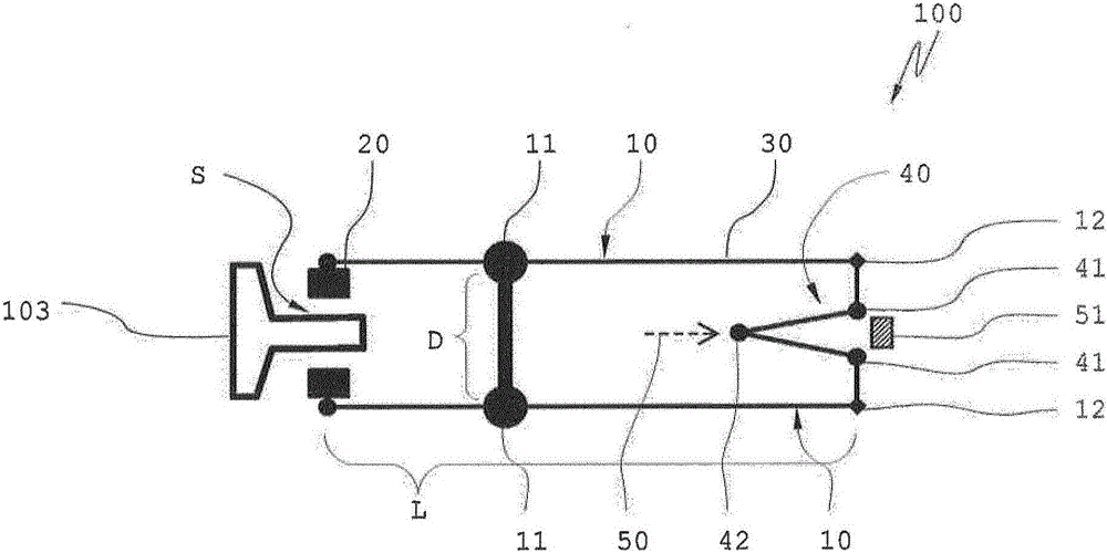
[0062] figure 1 A schematic view of a caliper brake 100 according to the invention is shown in a ready position. Caliper brake 100 has two brake calipers 10 which each have a pivot point 11 . The pivot point 11 is connected to the brake housing (not shown here). The two pivot points 11 of the brake caliper 10 have a distance D from one another. Here, the two brake calipers 10 are shown substantially parallel and in the standby position. The brake caliper 10 has a brake lining 20 at one end and a hinge point 12 at the other end. The brake arm 30 is located between the pivot point 11 and the hinge point 12 . The toggle hinge point 41 is located on the hinge point 12, and the toggle hinge point is connected with the toggle lever 40. The stop 51 is shown schematically. The brake caliper 10 has a length L. As shown in FIG. A guide rail 103 of the elevator is located between the two brake linings 20 of the brake caliper 10 . Between the guide rail 103 and the brake lining 20...


PUM


Abstract

The invention relates to a caliper brake (100) for elevator installations, comprising at least one and preferably two brake calipers (10). Each brake caliper comprises at least one brake pad (20) and a brake arm (30) as well as a fulcrum (11). At least one brake caliper can be pivoted in at least one stand-by position and in a braking position. At least one brake arm (30) is resilient and is preferably at least partly designed as a leaf spring.

Description

technical field [0001] The invention relates to a caliper brake for an elevator installation, a method for applying a contact force in a caliper brake and an elevator installation with a caliper brake, which have the preambles of the independent claims feature. Background technique [0002] Various devices are known from the prior art which are used as safety brakes in elevator installations. Safety brakes are known in different types, for example as wedge brakes, eccentric brakes or also caliper brakes. [0003] A caliper brake for an elevator system is known from EP 1657204 A2, which brake transmits the force of a spring energy store to a brake caliper by means of a toggle mechanism. A disadvantage of this caliper brake is, for example, the fact that the spring accumulator is loaded during the entire braking operation. Depending on the precision of the guide rail on which the caliper brake engages, there is the risk that the spring accumulator is loaded with different f...

Claims


Application Information

Patent Timeline
Patent Type & Authority Applications(China)
IPC IPC(8): B66B5/18
Inventor 约瑟夫·胡斯曼
Owner INVENTIO AG
Why Eureka
Try Eureka