Surface structure and manufacturing method of electric mosquito swatter

An electric mosquito swatter and surface structure technology are applied to devices, applications, and animal husbandry for capturing or killing insects. Excellent waterproof insulation performance, the effect of reducing labor costs

Active Publication Date: 2018-11-27
FUJIAN NASHIDA ELECTRONICS INC CO
View PDF10 Cites 0 Cited by
  • Summary
  • Abstract
  • Description
  • Claims
  • Application Information

AI Technical Summary

Problems solved by technology

[0002] Most of the existing electric mosquito swatters on the market are electric mosquito swatters with a three-layer mesh structure. It is relatively sparse, and the inner metal grid is relatively dense. The distribution of the three layers of electrodes is positive, negative, positive or negative, positive, and negative. Mosquitoes must touch the metal parts of the inner and outer layers of the mesh at the same time to be killed by electricity. For some Small pests crawling on the ground or walls (such as small cockroaches, centipedes, etc.), when the electric mosquito swatter with a three-layer mesh structure is buckled, it cannot form a circuit between the positive and negative electrodes through the body of the small pests, so the three-layer The electric mosquito swatter with mesh structure can only kill mosquitoes, but cannot kill small pests crawling on the ground or walls. At the same time, it is arranged in three layers in space, resulting in a thicker and cumbersome overall swatter surface, which is inflexible to use.
There were also single-layer electric mosquito swatters on the market more than ten years ago. The mesh surface is composed of more than 40 steel wires, which are evenly arranged in parallel on the same plane. Each adjacent steel wire is positive, negative, Positive and negative arrangement, the single-layer mesh electric mosquito swatter with this structure can form a circuit between the positive and negative electrodes through the body of small pests when the surface of the swatter is buckled, so it can not only beat mosquitoes but also kill mosquitoes crawling on the ground or The small pests on the wall have a thinner and lighter overall surface, and are more flexible and convenient to use, but because the manufacturing process is very complicated, first of all, more than 40 steel wires must be placed on the corresponding positions of the lower frame one by one, and then The ends of more than 40 steel wires are welded to the positive or negative electrode leads one by one, and then the upper frame is fastened to the lower frame, and then the upper frame and the lower frame are bonded. The single-layer mesh of this structure The surface electric mosquito swatter requires a lot of labor. The current labor cost is almost ten times higher than that of 20 years ago. The current labor cost can no longer support the surface structure of the original single-layer electric mosquito swatter.

Method used


Image

  • Surface structure and manufacturing method of electric mosquito swatter
  • Surface structure and manufacturing method of electric mosquito swatter
  • Surface structure and manufacturing method of electric mosquito swatter

Examples


Embodiment Construction

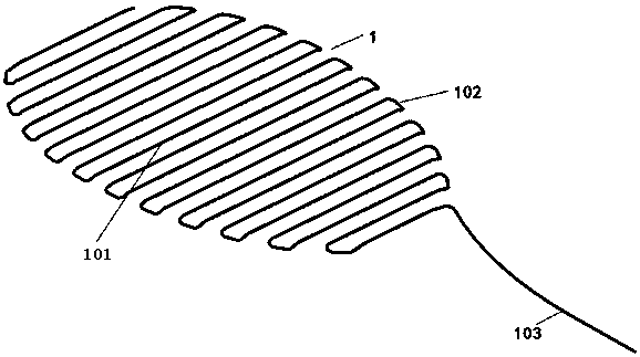
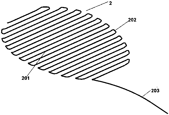
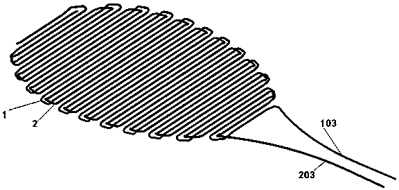
[0018] Such as Figure 1-5 As shown, a racket surface structure of an electric mosquito racket includes a racket frame 3, a mesh surface A1 and a mesh surface B2 arranged in the racket frame 3. The mesh surface A1 and the mesh surface B2 are each reciprocally bent by a metal wire A mesh surface is formed. The mesh surface A1 includes a number of parallel and evenly spaced horizontal portions A101. The adjacent horizontal portions A101 are connected by inflection portions A102. The mesh surface B2 includes a number of parallel and evenly spaced horizontal portions B201. The adjacent horizontal part B201 is connected by the inflection part B202. The end of the last horizontal part A101 is connected to the extension lead A103, and the end of the last horizontal part B201 is connected to the extension lead B203. The mesh surface A1 and the mesh surface B2 are parallel Staggered installation on the same plane, the mesh surface B2 is located above the mesh surface A1, the horizontal ...


PUM


Abstract

A racket head structure of an electric flyswatter, and a manufacturing method therefor. The racket head structure comprises: a racket frame (3), a net A (1), and a net B (2). The net A (1) and the net B (2) respectively consist of a metal wire bent back and forth to form a net. The net A (1) comprises several evenly spaced and parallel horizontal parts A (101). The adjacent horizontal parts A (101) connect to each other through a turning part A (102). The net B (2) comprises several evenly spaced and parallel horizontal parts B (201). The adjacent horizontal parts B (201) connect to each other through a turning part B (202). An end of the horizontal part A (101) located at the far most end connects to an extension lead A (103). An end of the horizontal part B (201) located at the far most end connects to an extension lead B (203). The net A (1) and the net B (2) are installed on the same plane in a parallel and alternating arrangement, with the net B (2) located above the net A (1). The horizontal part A (101) is located within an area between the adjacent horizontal parts B (201). The horizontal part B (201) is located within an area between the adjacent horizontal parts A (101). The net of the racket head structure is formed by winding two metal wires. The net has a sound structure and excellent waterproof and insulating properties, has a simple and reasonable manufacturing technique, and can electrocute a flying or land-bound bug.

Description

Technical field [0001] The invention relates to a racket surface structure and a manufacturing method of an electric mosquito racket. Background technique [0002] Most of the electric mosquito swatters on the market are three-layer nets. Each net uses a metal mesh structure, which is arranged in three layers in space, with two metal meshes on the outside. Relatively sparse, the inner metal grid is relatively dense, the distribution of the three layers of electrodes are positive, negative, positive or negative, positive and negative. Mosquitoes must contact the metal parts of the inner and outer mesh surfaces at the same time to be killed by electricity. Small pests crawling on the ground or wall (such as small cockroaches, centipedes, etc.), when the three-layer net structure of the electric mosquito swatter is buckled, they cannot form a loop between the positive and negative electrodes through the body of the small pest, so the three-layer The electric mosquito racket with ne...

Claims


Application Information

Patent Timeline
Patent Type & Authority Patents(China)
IPC IPC(8): A01M3/02
CPCA01M1/22A01M3/02
Inventor 林翠雯陈江群林洲
Owner FUJIAN NASHIDA ELECTRONICS INC CO
Why Eureka
Try Eureka