Cleaning mechanism with water spraying function and photovoltaic panel cleaning equipment provided with mechanism

A cleaning mechanism and photovoltaic panel technology, applied in the field of solar power generation, can solve the problem that the cleaning mechanism does not have the function of water spraying, and achieve the effects of preventing idling, improving power generation efficiency, and reducing wear

Active Publication Date: 2016-08-10
BOSON ROBOTICS LTD
View PDF4 Cites 7 Cited by
  • Summary
  • Abstract
  • Description
  • Claims
  • Application Information

AI Technical Summary

Problems solved by technology

The cleaning mechanism in the existing cleaning equipment does not have the function of spraying water

Method used


Image

  • Cleaning mechanism with water spraying function and photovoltaic panel cleaning equipment provided with mechanism
  • Cleaning mechanism with water spraying function and photovoltaic panel cleaning equipment provided with mechanism
  • Cleaning mechanism with water spraying function and photovoltaic panel cleaning equipment provided with mechanism

Examples


Embodiment 1

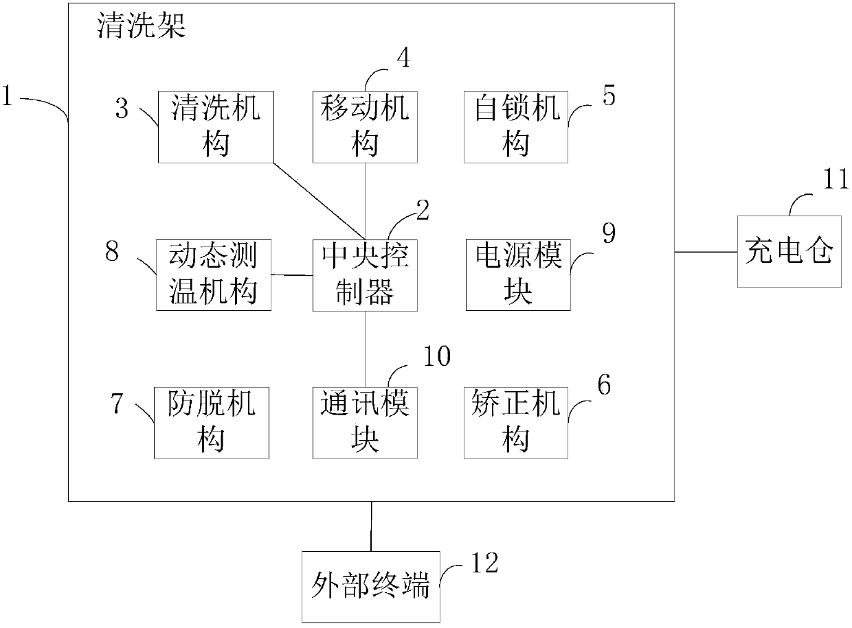
[0040] Such as figure 1 As shown, it is a functional block diagram of a photovoltaic panel cleaning device disclosed in the present invention. The photovoltaic panel cleaning device includes: a main body, a charging compartment 11 and an external terminal 12 . The main body includes: a cleaning frame 1, a central controller 2, a cleaning mechanism 3, a moving mechanism 4, a self-locking mechanism 5, a correction mechanism 6, an anti-off mechanism 7, a dynamic temperature measurement mechanism 8, a power module 9 and a communication module 10. Among them, the central controller 2, the cleaning mechanism 3, the moving mechanism 4, the self-locking mechanism 5, the correction mechanism 6, the anti-off mechanism 7, the dynamic temperature measurement mechanism 8, the power module 9 and the communication module 10 are all arranged on the cleaning frame 1. The cleaning mechanism 3 is connected with the central controller 2 for cleaning the photovoltaic panels. The moving mechanism ...

Embodiment 2

[0078] like Figure 18 As shown, it is a functional block diagram of another photovoltaic panel cleaning equipment disclosed in the present invention. The difference between the photovoltaic panel cleaning equipment disclosed in this embodiment and the first embodiment is that the photovoltaic panel cleaning equipment disclosed in this embodiment also includes : Obstacle-surmounting mechanism 13 and the telescopic mechanism 14 that are arranged on the washing frame 1. The obstacle-breaking mechanism 13 is used to make the body pass through the space between the two photovoltaic panel arrays smoothly. The telescoping mechanism 14 is connected with the central controller 2, and is used to move the body on the obstacle-breaking mechanism 13, and cooperate with the obstacle-breaking mechanism 13 to make the body smoothly pass through the space between two misplaced photovoltaic panel arrays.

[0079] Sometimes, due to not only a certain distance between photovoltaic panel arrays,...


PUM


Abstract

The invention discloses a cleaning mechanism with a water spraying function and photovoltaic panel cleaning equipment provided with the mechanism. The mechanism comprises a cleaning frame, a cleaning part, a sweeping part, a water spraying device and a cleaning part power unit, wherein the cleaning frame comprises a first connecting rod, a second connecting rod, a third connecting rod and a fourth connecting rod which can be detachably connected; the cleaning part can be detachably mounted between the first connecting rod and the third connecting rod, and is used for peeling off attachment on a photovoltaic panel; the sweeping part can be detachably mounted on the second connecting rod and the fourth connecting rod, and is used for sweeping the attachment from the photovoltaic panel; the water spraying device can be detachably mounted on the cleaning frame, and is used for wetting the attachment on the photovoltaic panel; the cleaning power unit can be detachably connected with the cleaning part, and is used for driving the cleaning part to rotate; and the cleaning part power unit comprises a self-locking device which is used for preventing the cleaning part from idling. Compared with the prior art, the cleaning mechanism can improve the cleaning effect, and can cool the photovoltaic panel, so that the power generation efficiency is improved.

Description

technical field [0001] The invention relates to the technical field of solar power generation, in particular to a cleaning mechanism with a water spray function and photovoltaic panel cleaning equipment with the mechanism. Background technique [0002] With the overall development of global industrialization, the demand for energy in various industries in various countries has expanded rapidly, and the amount of energy demand has become a standard for measuring the economic development of a country or region. Renewable energy mainly includes water energy, solar energy, wind energy, geothermal energy, biomass energy and other energy forms. Its biggest feature is its self-recovery ability. In the process of people's use, renewable energy can be continuously replenished from nature. , it is inexhaustible and inexhaustible energy. After scholars' research and demonstration, it is generally believed that solar energy and wind energy are the most effective and feasible energy typ...

Claims


Application Information

Patent Timeline
Patent Type & Authority Applications(China)
IPC IPC(8): B08B11/04B08B1/00B08B1/04B08B3/02H02S40/10
CPCB08B1/002B08B1/04B08B3/024B08B11/04H02S40/10Y02E10/50B08B7/04B08B2203/0223B08B2220/01
Inventor 王观宇张经功钱志宏
Owner BOSON ROBOTICS LTD
Why Eureka
Try Eureka