Polarizer and method of producing the same

A manufacturing method and technology for polarizers, which are applied to manufacturing tools, polarizing elements, grinding/polishing equipment, etc., can solve the problems of reducing the quality of polarizers, reducing dimensional accuracy, and reducing display performance, etc.

Inactive Publication Date: 2016-08-10
SUMIKA TECH
View PDF10 Cites 9 Cited by
  • Summary
  • Abstract
  • Description
  • Claims
  • Application Information

AI Technical Summary

Problems solved by technology

[0004] However, when the aforementioned cutting process is performed, due to the relatively flexible mechanical properties of the polarizer, the pressure applied during cutting will cause a slight deviation of each polarizer of the laminate, which will reduce the dimensional accuracy after cutting. Thereby r...

Method used


Image

  • Polarizer and method of producing the same
  • Polarizer and method of producing the same
  • Polarizer and method of producing the same

Examples


Embodiment 1

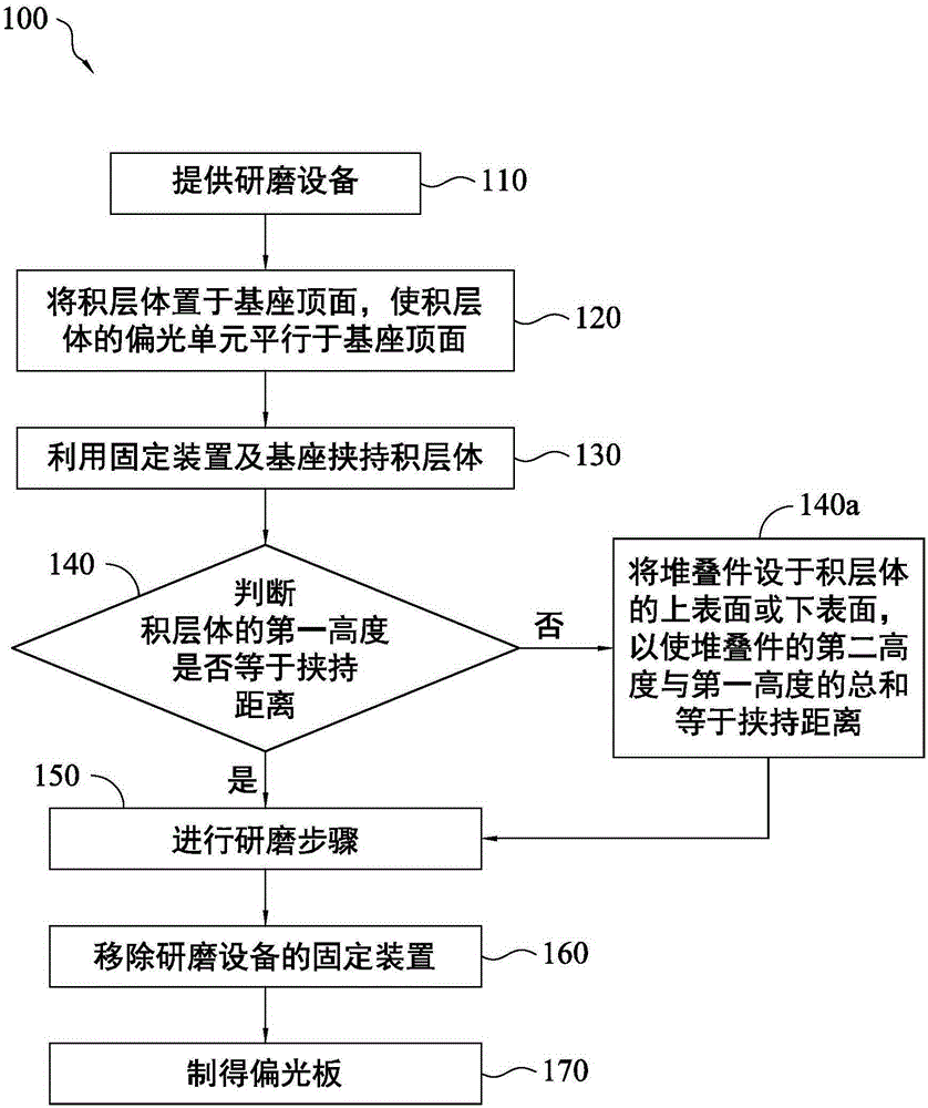
[0092] Please also refer to Figure 3a to Figure 3c , the laminated body 300 is first placed on the base 210, and the laminated body 300 is clamped by the fixing device 220 and the base 210, wherein the laminated body 300 includes a plurality of polarizing units 310, and these polarizing units 310 each include at least one An adhesive film 310b is layered, and the adhesive film 310b is disposed between the optical film 310a and the release layer 310c. In this embodiment, the first height H1 of the laminated body 300 is equal to the holding distance D between the fixing device 220 and the base 210 .

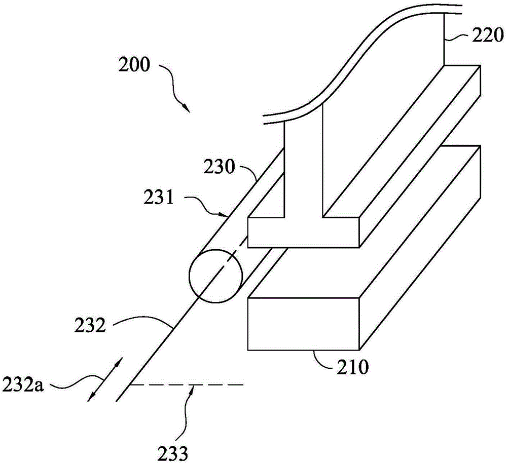
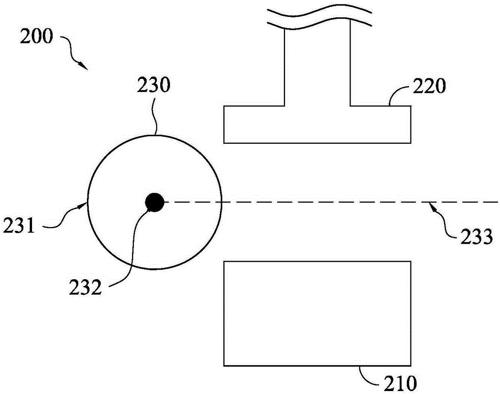
[0093] Then, the laminated body 300 was ground with the grinding surface 231 of the grinding device 230 at a cutting angle θ of 70°. After the grinding step, the polarizing plate of Example 1 can be obtained, and its structure is as follows Figure 5a shown. The obtained polarizing plate was evaluated by the following evaluation methods, and the evaluation results are shown in ...

Embodiment 2 to Embodiment 6 and comparative example 1 to comparative example 4

[0095] Example 2 to Example 6 and Comparative Example 1 to Comparative Example 4 used the same method as Example 1 to prepare polarizing plates. The difference is that Example 2 to Example 6 and Comparative Example 1 to Comparative Example 4 use different cutting angles to polish laminates 300 with different structures, wherein when the polarizing unit 310 includes two layers of adhesive films, these adhesive films are respectively It is arranged on both sides of the optical film, and in the adhesive film, there is a release layer on the other side away from the optical film. The structure diagram after its manufacture is as follows Figure 5b shown. The conditions and evaluation results of Example 2 to Example 6 and Comparative Example 1 to Comparative Example 4 are shown in Table 1, and will not be repeated here.

[0096] Evaluation method

[0097] 1. Grinding quality

[0098] For the polarizers prepared in Examples 1 to 6 and Comparative Examples 1 to 4, the grinding qua...


PUM


Abstract

A polarizer and a method of producing the same are provided. A laminated body is clamped by a fixing device and a base of a grinding apparatus. And then, an edge of the laminated body is grinded by a grinding surface of a grinding device of the grinding apparatus with a given entrance angle to produce the polarizer with a great size precision.

Description

technical field [0001] The invention relates to a polarizing plate and a manufacturing method thereof, and in particular to a polarizing plate with good dimensional accuracy and no glue overflow and a manufacturing method thereof. Background technique [0002] The polarizer in the display can change the polarization direction of light, thereby improving the performance of the display, and achieving different display technologies, such as three-dimensional display or liquid crystal display. Generally, the existing polarizing plate includes a polarizing film, an adhesive layer and a release layer, and the adhesive layer is disposed between the polarizing film and the release layer. Among them, the polarizing film can be attached to other optical films through the adhesive layer, and the release layer can prevent the adhesive layer of the polarizing plate from sticking to other objects, thereby improving the convenience of transportation of the polarizing plate. [0003] In or...

Claims


Application Information

Patent Timeline
IPC IPC(8): B24B37/00B24B37/005B24B9/10G02B5/30
CPCB24B9/10B24B37/00B24B37/005G02B5/30
Inventor 陈志添黄怡菱陈彦年李愷澄
Owner SUMIKA TECH
Why Eureka
Try Eureka