
Waterproof auxiliary frame for buildings as well as machining and mounting methods of auxiliary frame

A technology for construction and auxiliary frames, which is applied in the direction of buildings, building components, building structures, etc. It can solve the problems of large deformation, strong thermal conductivity and leakage of metal auxiliary frames, and achieve excellent windproof effect

Inactive Publication Date: 2016-08-10
舟山市东巨新型建筑材料有限责任公司
View PDF5 Cites 4 Cited by
  • Summary
  • Abstract
  • Description
  • Claims
  • Application Information

AI Technical Summary

Problems solved by technology

[0003] But in fact, the auxiliary frame is not necessarily good for the sealing, heat preservation and heat insulation of doors and windows, especially the metal auxiliary frame has strong thermal conductivity, large deformation, easy corrosion, and low affinity with cement mortar. If it is not handled properly, it is prone to leakage and other phenomena

Method used


Image

  • Waterproof auxiliary frame for buildings as well as machining and mounting methods of auxiliary frame
  • Waterproof auxiliary frame for buildings as well as machining and mounting methods of auxiliary frame
  • Waterproof auxiliary frame for buildings as well as machining and mounting methods of auxiliary frame

Examples


Embodiment 1

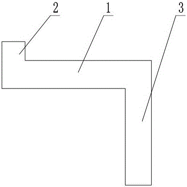
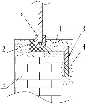
[0023] In embodiment one, if figure 1 , figure 2 As shown, it includes a backing plate 1 for positioning doors and windows, an inner baffle 2 close to the indoor side of the door and window, and an outer baffle 3 close to the outer wall of the hole; the inner baffle 2 covers the backing plate 1 and the The gap between doors and windows, the outer baffle plate 3 covers the gap between the backing plate 1 and the hole. Embodiment 1 The inner baffle plate 2 is used to block the gap between the backing plate 1 and the window a, and the outer baffle plate 3 is used to block the gap between the backing plate 1 and the opening wall b, effectively separating the indoor from the outdoor and preventing rainwater, etc. It leaks into the room from various gaps, and has excellent windproof, waterproof and anticorrosion properties.

[0024] In the first embodiment, if figure 1 As shown, the backing plate 1, the inner baffle 2 and the outer baffle 3 are integrally formed. The present in...

Embodiment 2

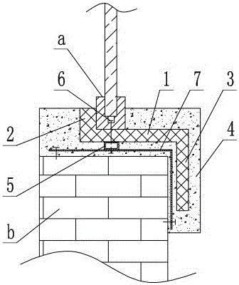
[0029] In the second embodiment, if image 3 , Figure 4 As shown, several anchors 5 are installed on the side of the backing plate 1 close to the hole, screws 6 for anchoring doors and windows are fixed on the top of the anchors 5, and a tie belt 7 is fixed below the anchors 5, so Said tie belt 7 is anchored in said cement mortar layer 4 . Compared with the structure of the embodiment 2, the installation of the auxiliary frame is more firm. The anchor piece 5 and the pull-joint 7 can be glued together, or can be connected with screws and iron nails. The window can be directly fixed on the anchor piece 5 with the screw 6, or the screw 6 and the window can be clamped together with a V-shaped clamp. Wherein the anchor piece 5 is preferably made of an aluminum alloy, and the tie strap 7 is preferably made of a metal material such as a steel strip.

[0030] In the second embodiment, the distance between two adjacent anchor pieces 5 is less than or equal to 50 cm. In the secon...


PUM

PropertyMeasurementUnit
Thicknessaaaaaaaaaa
Heightaaaaaaaaaa
Heightaaaaaaaaaa

Abstract

The invention discloses a waterproof auxiliary frame for building and its processing and installation method, which is mainly used to improve the windproof, leakage-proof and anti-corrosion performance of the auxiliary frame. The inner baffle on the indoor side and the outer baffle close to the outer wall of the hole; the inner baffle covers the gap between the backing plate and the door and window, and the outer baffle covers the gap between the backing plate and the hole. The invention uses the inner baffle to block the gap between the backing plate and the door and window, uses the outer baffle to block the gap between the backing plate and the hole, effectively separates the indoor from the outdoor, prevents rainwater from leaking into the room from various gaps, and has excellent performance. Windproof and waterproof performance.

Description

technical field [0001] The invention relates to the field of construction and decoration, in particular to a waterproof auxiliary frame for construction and methods for processing and installing the same. Background technique [0002] Auxiliary frame, also known as auxiliary frame and auxiliary frame, plays the role of sizing and positioning for doors and windows. Generally speaking, after the building's door and window openings are completed, the size is not standardized, so large-scale projects or high-quality projects require the installation of auxiliary frames. After the processing of the hole is completed or is about to be completed, the auxiliary frame is installed, and the positioning of the auxiliary frame is completed, the size and position of the door and window are determined, which is more standardized. At the same time, the use of auxiliary frames makes it easier to control the installation quality of doors and windows, and also reduces the expansion and contr...

Claims


Application Information

Patent Timeline
IPC IPC(8): E06B1/02E06B1/58E06B1/60
CPCE06B1/02E06B1/58E06B1/6015
Inventor 张敬科
Owner 舟山市东巨新型建筑材料有限责任公司
Learn More