Composite arch tunnel lining structure with water-repellent function

A functional, box-type technology, applied in the direction of tunnel lining, tunnel, shaft lining, etc., can solve the problems of rising groundwater level, stagnant water cannot be effectively drained, and drainage system cannot be drained in time

Active Publication Date: 2018-09-21
CHINA RAILWAY ERYUAN ENG GRP CO LTD
View PDF7 Cites 0 Cited by
  • Summary
  • Abstract
  • Description
  • Claims
  • Application Information

AI Technical Summary

Problems solved by technology

The biggest defect of the traditional drainage system is that the central ditch is set inside the tunnel structure, mainly to drain and drain the surrounding groundwater in the area of ​​the main arch wall, and the accumulated water below the inverted arch of the tunnel cannot be effectively drained
Especially in areas with close hydraulic connection of the foundation, in continuous rainfall or rainstorm weather, due to the sudden increase in the amount of groundwater, the traditional drainage system often cannot lead the drainage to the drainage ditch in the tunnel structure in time, resulting in a sharp rise in the groundwater level

Method used


Image

  • Composite arch tunnel lining structure with water-repellent function
  • Composite arch tunnel lining structure with water-repellent function
  • Composite arch tunnel lining structure with water-repellent function

Examples


Embodiment Construction

[0015] The present invention will be further described below in conjunction with the accompanying drawings and embodiments.

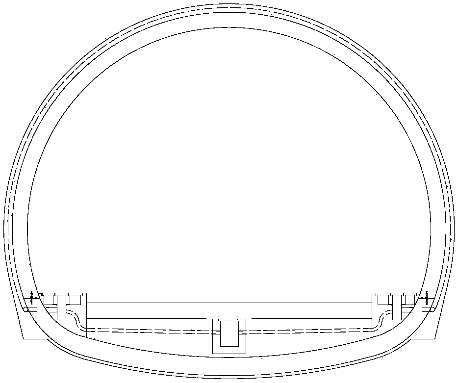
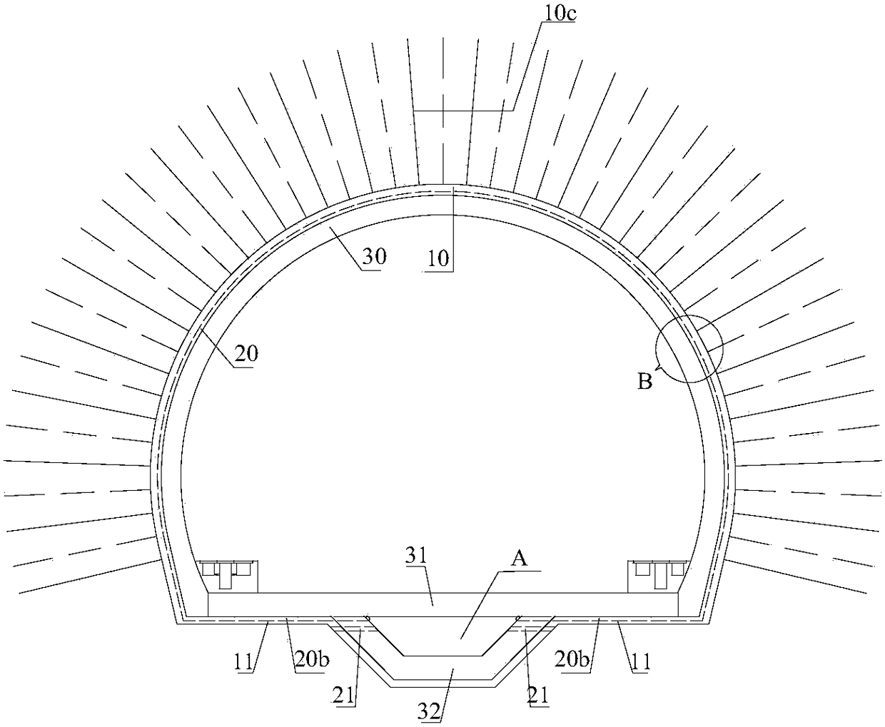
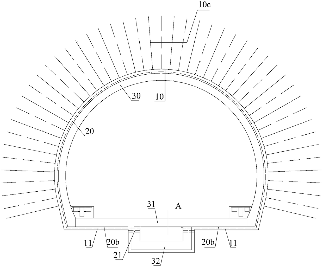
[0016] refer to figure 2 and image 3 , the box-type tunnel bottom composite arched tunnel lining structure with water-repelling function of the present invention includes an arch wall initial support structure 10, a secondary lining structure and a base leveling layer 11 arranged from outside to inside, and is arranged on the arch wall initial support structure. The waterproof and drainage system 20 between the structure 10 and the secondary lining structure communicates with the central drainage groove A. The secondary lining structure includes a secondary lining 30 of the arch wall and a box-shaped floor structure composed of a bottom plate 31 and a groove plate 32. The two ends of the bottom plate 31 are consolidated with the bottom end of the secondary lining 30 of the arch wall, and the groove plate 32 is opposite to each other. A central drain...


PUM


Abstract

The invention discloses a box type tunnel-bottom composite arched tunnel lining structure with a water drain function, so as to effectively prevent underground water from being introduced into a tunnel, to overcome the immersion, which is caused as the water discharge capacity of side ditches and a central ditch in the tunnel are insufficient in a rainfall-flood season, of a road bed by the underground water, and to guarantee that an underground water level is lower than the bottom plate of the tunnel, thereby removing the risk that the underground water destroys a lining structure, particularly a tunnel-bottom structure, in the rainfall-flood season. The box type tunnel-bottom composite arched tunnel lining structure with the water drain function comprises an arch wall primary supporting structure, a secondary lining structure and base leveling layers, wherein the arch wall primary supporting structure, the secondary lining structure and the base leveling layers are arranged from exterior to interior; a waterproof water drain system arranged between the arch wall primary supporting structure and the secondary lining structure communicates with a central water discharge channel. The secondary lining structure comprises an arch wall secondary lining and a box type bottom plate structure which consists of a bottom plate and a channel plate; the two ends of the bottom plate are fixedly connected with the bottom end of the arch wall secondary lining; the channel plate is sunken relative to the plate surface of a top plate to form the central water discharge channel. The upper parts of two side walls of the channel plate are provided with water sluicing pipes which are buried at intervals along the extension direction of a line; the inner end of each water sluicing pipe communicates with the central water discharge channel; the outer end of each water sluicing pipe penetrates through the base leveling layers to a base of the tunnel.

Description

technical field [0001] The invention relates to a tunnel lining structure, in particular to a tunnel lining structure under the condition that underground water develops or is greatly influenced by seasons and has no high ground stress geology. Background technique [0002] In the 21st century, with the rapid development of my country's railway construction, more and more high-standard double-track railways with a speed of more than 200km per hour have been built, especially in the central and western mountainous areas. Restricted by these factors, the scale of tunnels has increased rapidly, and there are more and more tunnels in large mountains. Due to the complexity, diversity and irregularity of groundwater development, the risk of long tunnel construction, especially the risk of water damage in operation, is getting higher and higher. [0003] The traditional double-lane tunnel lining generally adopts the lining structure with curved walls and inverted arches, such as f...

Claims


Application Information

Patent Timeline
Patent Type & Authority Patents(China)
IPC IPC(8): E21D11/00E21D11/10E21D11/38
CPCE21D11/00E21D11/10E21D11/38
Inventor 张磊卿伟宸林本涛高杨郑伟朱勇曾宏飞黄华钟昌桂孟祥磊张慧玲巩江峰王若晨
Owner CHINA RAILWAY ERYUAN ENG GRP CO LTD
Why Eureka
Try Eureka