Efficient double-piston hot-air engine

A dual-piston, hot-air engine technology, applied in hot-air variable-capacity engine installations, mechanical equipment, machines/engines, etc., can solve the problems of inconvenient angle fine-tuning, waste, and difficulty in the best working condition of the engine.

Active Publication Date: 2016-08-10
JINING XINRUIDA INFORMATION TECH CO LTD
View PDF10 Cites 2 Cited by
  • Summary
  • Abstract
  • Description
  • Claims
  • Application Information

AI Technical Summary

Problems solved by technology

[0002] Under the premise of a certain working fluid pressure and a certain temperature difference between the hot and cold ends, the main factors affecting the performance improvement of the hot air machine are the heat shuttling loss of the hot and cold end working fluid back and forth, and the useless volume loss. The volume of the traditional heater passes through the regenerator. The volume and the volume of the cooler are connected to each other, that is to say, when the heater heats and expands the working medium in the expansion chamber to push the p...

Method used


Image

  • Efficient double-piston hot-air engine
  • Efficient double-piston hot-air engine

Examples


Embodiment 1

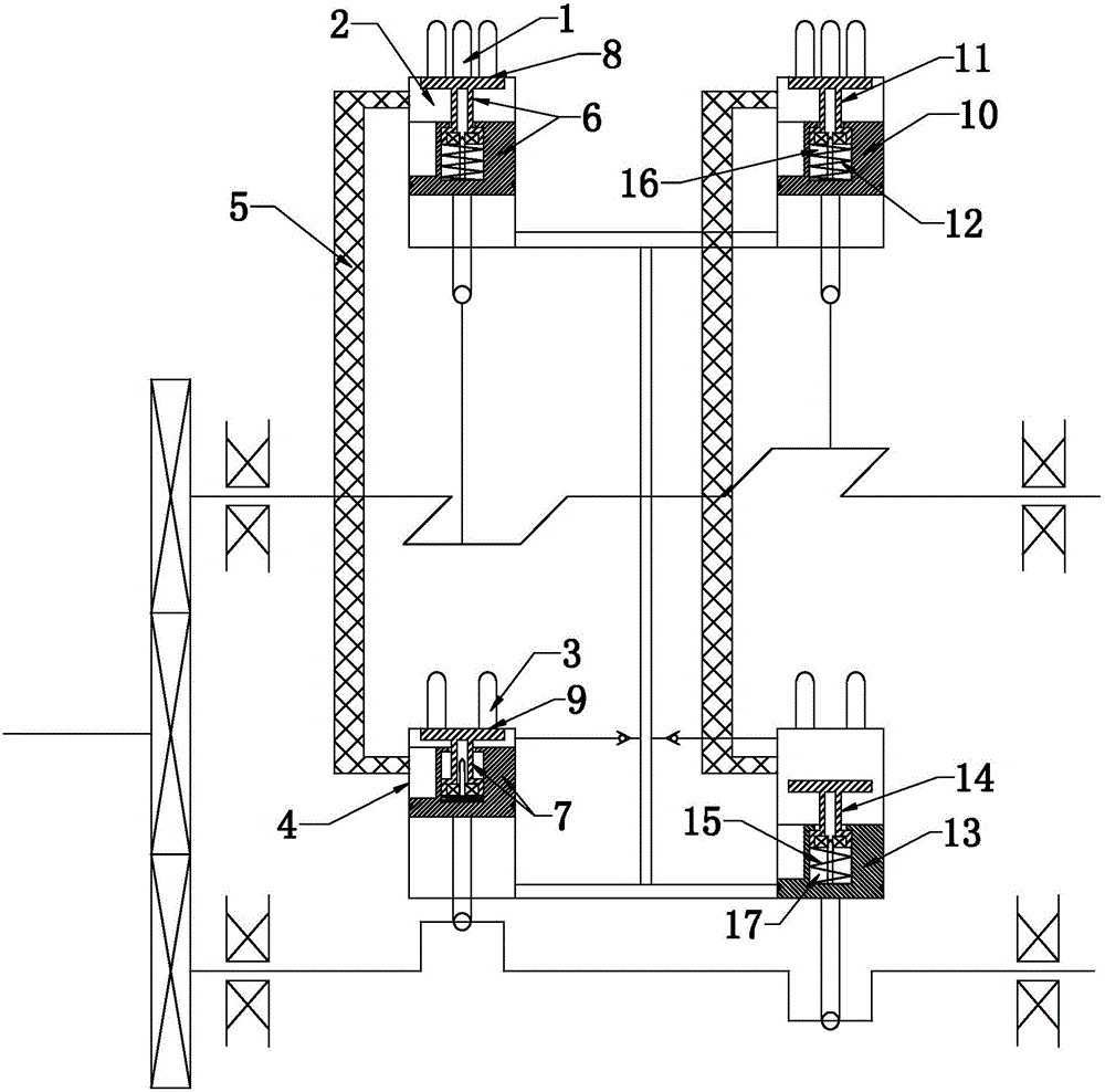
[0024] Such as figure 1 As shown, the high-efficiency dual-piston heat engine of the present invention includes an expansion chamber 2 with a heater 1 and a compression chamber 4 with a cooler 3. The expansion chamber 2 and the compression chamber 4 communicate through a regenerator 5, and the expansion chamber 2 The expansion piston 6 is arranged inside, and the compression piston 7 is arranged in the compression chamber 4. The expansion piston 6 and the compression piston 7 are respectively connected to the power output end, and the end of the expansion chamber 2 has heating sink holes 8 evenly arranged to cooperate with the end surface of the expansion piston. The end of the compression chamber 4 has cooling sink holes 9 that are evenly distributed and matched with the end face of the expansion piston. The expansion piston 6 includes an expansion piston body 10 and an expansion sealing door 11 that cooperates with the expansion piston body 10 and can slide back and forth rel...

Embodiment 2

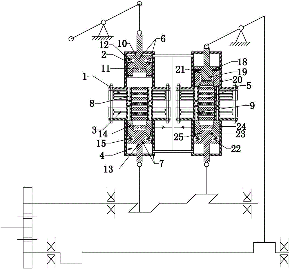
[0027] Such as figure 2As shown, the high-efficiency dual-piston heat engine of the present invention includes an expansion chamber 2 with a heater 1 and a compression chamber 4 with a cooler 3. The expansion chamber 2 and the compression chamber 4 communicate through a regenerator 5, and the expansion chamber 2 The expansion piston 6 is arranged inside, and the compression piston 7 is arranged in the compression chamber 4. The expansion piston 6 and the compression piston 7 are respectively connected to the power output end, and the end of the expansion chamber 2 has heating sink holes 8 evenly arranged to cooperate with the end surface of the expansion piston. The end of the compression chamber 4 has cooling sink holes 9 that are evenly distributed and matched with the end face of the expansion piston. The expansion piston 6 includes an expansion piston body 10 and an expansion sealing door 11 that cooperates with the expansion piston body 10 and can slide back and forth rel...


PUM


Abstract

The invention discloses an efficient double-piston hot-air engine. The efficient double-piston hot-air engine comprises an expanding cavity and a compression cavity, wherein the expanding cavity communicates with the compression cavity through a heat regenerator; an expanding piston is arranged in the expanding cavity; a compression piston is arranged in the compression cavity; the expansion piston and the compression piston are separately connected with a power output end; a heating counter bore and a cooling counter bore are separately formed in the expanding cavity and the compression cavity; a heater sealing door is arranged in the expanding piston; a heater compression spring is arranged in a heater sealing door mounting cavity; a cooler sealing door is arranged in the compression piston; a cooler compression spring is arranged in the cooler sealing door mounting cavity; and cylindrical grooves which communicate with the heat regenerator are separately formed in the expanding piston and the compression piston. After the structure is adopted, the purpose that the volume of a cooler is closed during working by heating and the volume of a heater is cooled during cooling compression is realized; besides, a phase angle between crankshafts on the power output shaft can be fine adjusted, so that the engine reaches the optimal working state.

Description

technical field [0001] The invention relates to a double-piston heat engine, in particular to a high-efficiency double-piston heat engine. Background technique [0002] Under the premise of a certain working medium pressure and a certain temperature difference between the hot and cold ends, the main factors affecting the performance improvement of the hot air machine are the heat shuttling loss of the hot and cold working medium airflow back and forth, and the useless volume loss. The volume of the traditional heater passes through the regenerator. The volume and the volume of the cooler are connected to each other, that is to say, when the heater heats and expands the working medium in the expansion chamber to push the piston to do work, another part of the high-temperature working medium gas is neutralized and cooled by the cooler through the regenerator, which is wasted and mainly useless The volume includes the sum of heater volume, regenerator volume, and cooler volume,...

Claims


Application Information

Patent Timeline
IPC IPC(8): F02G1/044F02G1/053
CPCF02G1/044F02G1/053
Inventor 夏致俊
Owner JINING XINRUIDA INFORMATION TECH CO LTD
Why Eureka
Try Eureka